


sludge drying and cogeneration
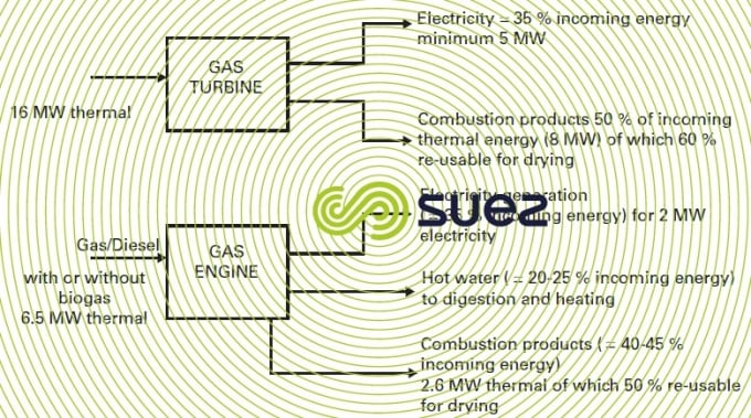
Reading time:Drying processes can be incorporated into cogeneration units by using the thermal energy generated by gas engines or gas turbines. The purpose of the following paragraphs (together with figure 21) is to define the main parameters and the general approach to be followed when this type of application is under consideration.
The following parameters are used to differentiate between gas engines and gas turbines:
- combustion products delivered by a gas engine usually have lower temperature characteristics than those delivered by gas turbines. However, in both cases, advanced energy re-use (boiler) can be considered;
- a gas engine dissipates a significant proportion of incoming energy (20 to 25%) as hot water. This hot water can be used efficiently when the site housing the drying system also has a digester. Thus, the entire biogas output can be used by the engine. However, we need to note that the drying process itself is capable of producing low calorie energy for use by the digestion function. Consequently, there will be excess energy and overall cost-effectiveness will be lower unless this excess energy can be used to heat buildings;
- on grounds of construction costs, gas engines are better suited to units having a low to medium energy capacity while gas turbines should be reserved to units with greater capacity.
When biogas is used as the sole or part source of energy, this biogas must first be dried and its sulphur content (and dust, if necessary) removed to prevent any acid corrosion and abrasion problems in the co-generation system.
Quite often, co-generation may be feasible on financial but not on technical grounds; feasibility will vary from one project to another, depending on primary energy specific costs and the income generated by the electricity produced. This feasibility must be examined for each individual case and may depend to a large extent on the credit side (green or sustainable energy).

With low temperature dryers, such as Evaporis™ LT, it is possible to optimise maximum recovery of the thermal energy produced by a gas engine, as shown in the diagram below:
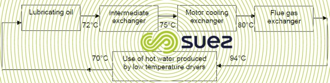
This thermal loop allows 46% of biogas energy to be recovered with 23% from energy in flue gas and the remaining 23% from the cooling motor, intermediary process and the oil loop.
Bookmark tool
Click on the bookmark tool, highlight the last read paragraph to continue your reading later
