


suspended growth (activated sludge) process (page 3)
sulphur bacteria
The sulphur cycle is a complex system. Sulphur exists in several types of biological molecules such as enzymes, certain amino-acids such as cysteine and methionine as well as in several vitamins such as biotine and thiamine.
Whilst it is essential for life, sulphur only represents between 1 and 2% of the mass (expressed in dry matter) of living beings.
In the environment, it is essentially present in the form of sulphate, in native form and in biological molecules.
Sulphur is present in all of its forms on Earth, which explains how bacteria have been able to colonise a large proportion of aquatic and terrestrial environments permitting them to resist high temperatures (sulphurous hot springs) and high pressures (depths of the ocean).
Within the sulphur cycle, five types of reactions exist:
- Assimilatory reduction of sulphide ions (transformed into organic matter: phytoplanction);
- Decay (these germs are aerobic heterotrophic bacteria which release hydrogen sulphide from proteins);
- Dissimilatory sulphate-reduction (anaerobic);
- Phototrophic oxidation of hydrogen sulphide;
- Oxidation of sulphur by heterotrophic or autotrohpic bacteria in the presence of oxygen or nitrates.
Sulphate-reducing bacteria are probably one of the oldest bacterial forms. This group of bacteria is uniformly present on the globe’s entire surface. Some of these bacteria are thermophilic, others are mesophilic or psychrophilic. We are also aware of a halophilic species.
Some strains are facultative autotrophs and others strict heterotrophs and use organic substrates as electron donors.
Depending on their carbonaceous metabolism, we can identify two bacterial groups within sulphate-reducing bacteria:
- the first group realises a complete oxidation of the organic substrate until the CO2 stage with the production of hydrogen sulphide;
- the second group oxidises organic matter in an incomplete manner until the acetate stage with the production of hydrogen sulphide.
Thiobacillus Denitrificans are part of the heterotrophic bacterial group whose common point is the capacity to use the reduced sulphur compounds as a source of energy in the presence of oxygen or nitrate. In the absence of oxygen and in the presence of nitrate, the final electron acceptor will be the nitrate which will be reduced into gaseous nitrogen (autotrophic denitrification).
These different principles can be used in wastewater treatment to eliminate carbon and nitrogen pollution.
biological phosphate removal
The possibility of using a biological method for removing phosphorus, i.e. without injecting any chemical reactors and producing virtually no additional sludge, was the object of much research work carried out from the mid 1960's onwards. Since, various activated sludge configurations, making use of all anaerobic phases followed by aerobic phases, have been developed and implemented on an industrial scale.
One of these configurations (Phostrip or A/O process) consists in removing phosphorous biologically and chemical without eliminating nitrogen. However, this paragraph will only address the processes that combine phosphorus and nitrogen removal through nitrification and denitrification.
process description
In biological phosphate removal, the phosphorus found in raw water is incorporated into the cell biomass and then discharged from the system with the excess sludge.
Some bacteria, known collectively as organisms, will accumulate phosphate (PAO in Anglo-Saxon literature) and have the interesting feature of being able to concentrate phosphorus in the form of polyphosphate granules as they are submitted to alternating anaerobic and aerobic conditions.
Thus, while the typical phosphorus composition of common heterotrophic bacteria will range from 1.5 to 2% of dry solids, PAO phosphorus content can reach 20-30%.
Biologically complex reactions that take place in each zone are outlined in figure 18 and can be described as follows:
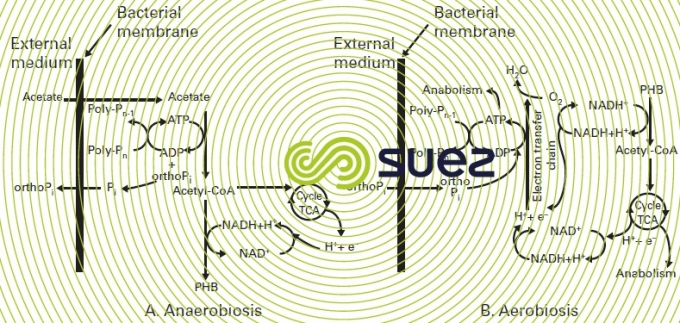

in an anaerobic zone
- acetate is produced as the rapidly biodegradable COD ferments (rb COD): the dissolved organic material that can easily be assimilated by the biomass). In effect, depending on the retention time in anaerobic conditions, a proportion of the particulate and colloidal COD may also be hydrolysed and converted into acetate;
- using energy available from polyphosphates (previously stored: see aerobic phase), the PAO assimilate acetate and glycogen contained in their cells and synthesise intracellular storage products, PHAs (Polyhydroxyalcanoate), the most important of which is PHB (Polyhydroxy butyrate).Simultaneously with the absorption of acetate, orthophosphate (ortho-P) will be released together with magnesium, potassium and calcium cations;
- consequently the PHB content of PAOs will increase as polyphosphates fall.
in aerobic/anoxic digestion zone
- the PHB that is stored is metabolised and thus supplies the energy and carbon required for new cell growth (glycogen is also produced from PHB metabolism);
- the energy supplied from the PHB is used to form polyphosphate bonds so that the soluble orthophosphate (ortho-P) is re-absorbed and included as polyphosphate inside the bacterial cell. This growth of a new biomass with a large store of polyphosphate explains why phosphorus is eliminated;
- finally, the intracellular phosphorus is discharged from the treatment reactor in the excess sludge.
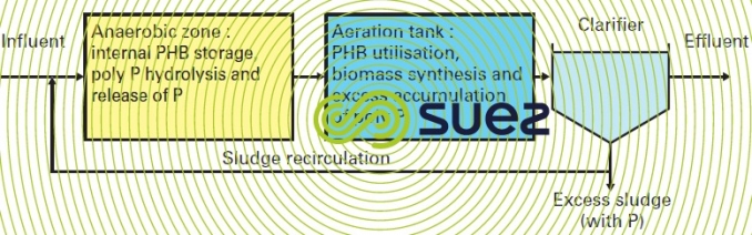
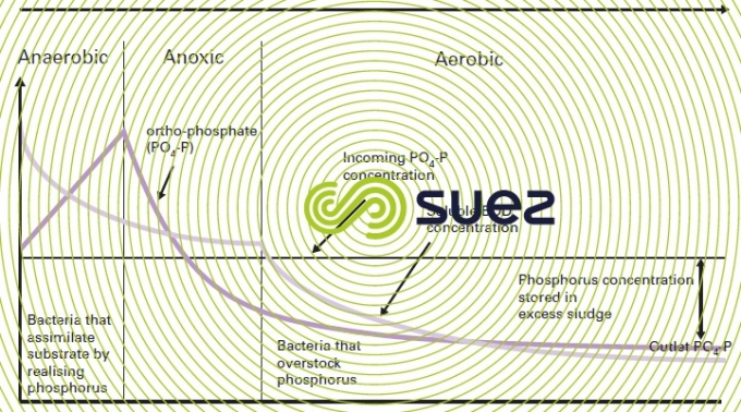
Figure 19 summarises the main treatment phases and figure 20 illustrates the concomitant progress of BOD and ortho-P through anaerobiosis and then anoxic and aeration.
dimensioning and operating parameters
The descriptions given below of the mechanisms involved are used to highlight those elements that will have an overriding impact on process effectiveness.
assimilable carbon in raw water
Assimilable carbon is the key point in the process because it triggers all organic polymer synthesising mechanisms. Therefore, the readily biodegradable carbon concentration in raw water (acetate, propionate and other volatile fatty acids) will directly determine the maximum quantity of phosphorus that could be eliminated biologically. Furthermore, the conversion of rb COD into VFA through anaerobic fermentation takes place quickly. It takes 7 to 10 mg of acetate or rb COD to eliminate 1 mg of P.
It is important to note that, as regards carbon availability, there are no major interactions between biological phosphorus removal and denitrification. In effect, the reactions that take place in anaerobic digestion conditions do not remove the organic pollution that is easily assimilable (with the exception of a small amount discharged as CO2); these reactions convert this organic pollution into intracellular polymers available for downstream denitrification reactions. On the other hand, denitrification kinetics in the anoxic zone are slightly weaker if it is preceded by an anaerobic zone.
Recently, SUEZ revealed the existence of biological phosphate removal based on the use of sulphides instead of and to replace rb COD. This phenomenon was observed at the Doha West facility, functioning at high temperature (25-38°C) and permanently in taking a significant quantity of sulphides (10-30 mg S/L).
dissolved oxygen and nitrates
Maintaining strict anaerobic conditions is obligatory for acetate product and PHB storage reactions to take place.
It is therefore compulsory for:
- the presence of dissolved oxygen to be avoided in the influent; for instance avoid an excessively intensive aeration of the influent before it enters into the anaerobic zone. If necessary, a pre-anoxia or a plug flow type inlet area will allow this oxygen to be consumed rapidly but to the detriment of a little rb COD;
- the presence of nitrates to be avoided in activated sludge recirculation. To achieve this, we either have to maintain the nitrates in the water to be treated at minimum levels or include supplementary recirculated sludge denitrification, whether endogenous or exogenous (please refer to the different schemes under suspended growth (activated sludge) process).
anaerobic zone capacity
Different approaches have been used to establish the volume of the anaerobic zone and especially: fraction of the anaerobic sludge mass in relation to the system’s total sludge mass, anaerobic contact time calculated either in relation to the raw water average throughput or in relation to the total flow transiting through the anaerobic zone.
The most straight or ward approach consists in defining a minimum anaerobic contact time calculated using the sum of the dry weather peak flow rate and the sludge recirculation flow rate. This contact time is set on the basis of the fraction of influent COD that can be broken down rapidly, on sludge concentration and nitrate concentration at the anaerobic zone intake.
With the exception of extremely favourable conditions, where the contact time can be less than 1 hour, as a rule the recommended contact time will be between 1 and 2 hours. The fraction of the associated anaerobic sludge mass varies between 10 and 20% of the total sludge mass in the biological reactor.
It should be noted that too long a period in anaerobic conditions can have a negative effect on expected performances (so-called secondary release).
managing excess sludge
Knowing that phosphorus release/absorption phenomena are reversible, sludge processing methods have to be chosen in such a way as to avoid the release and then the recycling of large quantities of soluble phosphorus at the station inlet.
This applies more especially to thickening processes: gravity thickening must be banned in favour of dynamic processes such as flotation, draining screen, centrifuges that avoid extended contact times in anaerobic conditions.
On the other hand, contrary to expectations, the amount of phosphorus released during anaerobic sludge digestion is significantly lower than that forecast.
In effect, phosphorus is indeed released but most of it will be precipitated by ions such as magnesium, ammonium and iron…, to form compounds such as struvite (Mg, PO4, NH4, 6H2O), brushite (Ca HPO4, 2H2O) or vivianite (Fe3(PO4)3, 8H2O) that remain trapped in the digested sludge.
process performances
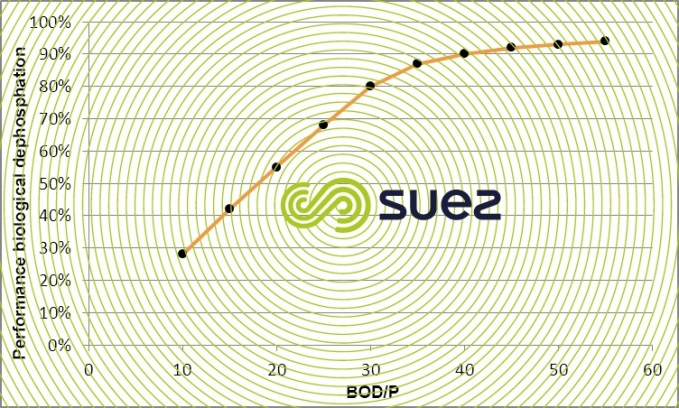
Phosphorus removal efficiency achieved using biological phosphate removal processes will vary more especially according to the influent’s rapidly biodegradable COD fraction and BOD/P ratio. Figure 21 provides an approximate figure for typical urban effluent in terms of its COD rb/total COD ratio (inclusive of inert phosphorus).
With an influent that has a low phosphorus content and a favourable BOD/P ratio (upper than 30), we can achieve a discharge that contains less than 1 mg · L–1 of total phosphorus. However, in the case of typical domestic water, this order of magnitude cannot be guaranteed without supplementary chemical precipitation.
Furthermore, daily influent concentration variations will affect phosphorus removal performance. Similarly, during rainfall episodes, and especially in cold weather, phosphate removal may prove difficult due to a rb COD concentration that is too low.
For all these reasons, any biological phosphate removal process must be combined with a supplementary chemical precipitation which can be simultaneous or tertiary in some cases.
main purification processes
Changes in our understanding of the mechanisms of biological phosphate removal over recent years have led to very different configurations with the twin aim: minimising nitrates added in the anaerobic zone and/or maximisation of volatile fatty acid formation in the anaerobic zone.
A selection of these processes is given below:
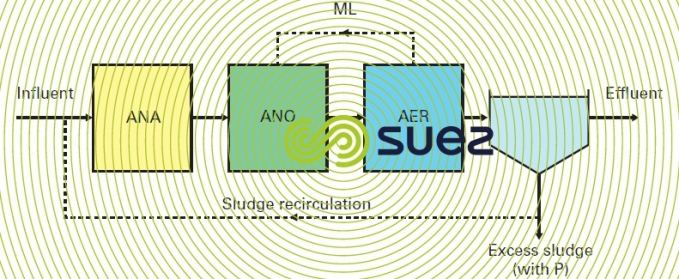
modified Phoredox process
This process (figure 22) uses the typical nitrification-denitrification concept with an anoxia zone at the inlet to which an upstream anaerobic zone is added. The simplicity of this scheme and its consistency with existing processes has led to its being the most widely used, in particular in France where it was selected for all the first plants. Its main downside is the actual concept of an anoxic zone at the inlet. This means that it is not always possible to maintain sufficiently low residual nitrate concentrations. Owing to this, a variation with upstream pre-anoxia has been developed over recent years.
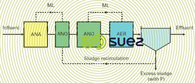
modified UCT (University of Cape Town) process
This scheme (figure 23) consists in separating the anoxic zone intended for clarifier sludge recirculation from the water treatment zone. Dimensioning of the "water" anoxic zone and mixed liquor recycling can only be calculated using residual nitrates. On the other hand, the principle behind this scheme creates an imbalance between sludge concentrations in the different tanks; the anaerobic zone will have a lower sludge concentration than the downstream tanks; consequently, in order to maintain a sludge mass under anaerobic conditions equivalent to that shown in the preceding scheme, the volume of this zone has to be increased.
JHB process (Johannesburg)
This configuration (figure 24) was used at the Johannesburg water treatment plant to avoid the negative impact created by nitrates. Sludge denitrification before penetrating into the anaerobic zone takes place.
Endogenously in a tank located on the recirculation line. The overriding problem continues to be regulation in this zone in order to ensure complete denitrification (variable contact time, possible shortfall in assimilable carbon).
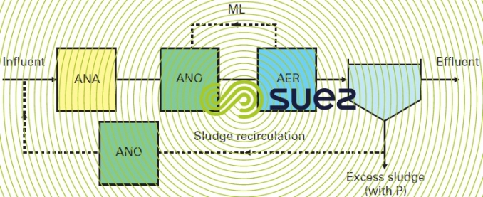
A variation of this process has been implemented at the Valenton facility. It consists in introducing a raw water fraction in endogenous denitrification (a maximum of 30%), which permits sludge recycling denitrification to be permanently managed and a nitrate-free liquor to be introduced during anaerobia.
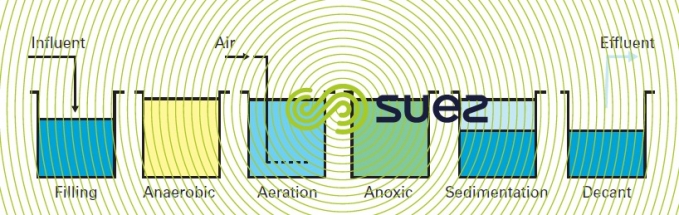
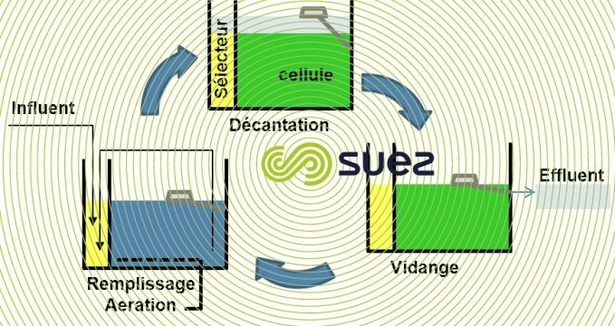
SBR process with biological phosphate removal (figure 25)
In an SBR (see sequencing batch reactor process), elimination of the nitrates formed can be achieved using appropriate aeration sequencing during the reaction process and completed during sedimentation and drainage periods.
During the fill period, a fraction of the sludge is recirculated towards the selector which serves as an anaerobic zone (hydraulic residence time of approx. 45 minutes). Nitrate concentration levels and the flow recirculated during the cycle being low, anaerobic conditions during the fill and initial reaction period are maintained within the selector. This encourages rb COD adsorption and storage phenomena instead of rb COD being consumed by denitrifying bacteria. This is the case of the Cyclor.
Other approaches aiming to modify the cycle by creating an anaerobic period with feeding at the beginning of the cycle are possible, but make denitrification difficult (which consequently occurs after an aerated phase during which the carbon is consumed with the oxygen). They also make it difficult to optimise dimensioning at a hydraulic level as the duration of the cycle increases the volume to be stored, resulting in high volume fluctuation.
other existing schemes
Among other existing schemes, some are designed to remedy an assimilable carbon shortfall in the anaerobic digestion zone:
- either through the direct injection of an external source of carbon (acetic acid or ethanol molasses);
- or through the controlled fermentation of primary sludge and by sending the resulting supernatant liquor into the anaerobic zone (beware of odours and of sludge dewatering problems).
modelling and its applications in UWW
dimensioning activated sludge plants
Given the complex nature of schemes and the low figures that have to be met on discharges, we are increasingly having to dimension a plant as closely as possible on the basis of mathematical models (software packages) that describe the equilibrium operation state of the various processes present in the plant and do so
- based on fundamental data applicable to the plant and on the standards to be satisfied;
- for the scenario identified by the designer thus enabling him to select the best of these.
biological processes describe the dimensioning tools currently used by SUEZ.
dynamic simulation
If we examinean individual plant’s behaviour under different operating conditions, we need a dynamic simulation (that is to say one that incorporates the fluctuations in raw water qualities and changes in operating parameters over time), in other words, modelling.
The main application of modelling consists in testing different scenarios on a plant that has already been dimensioned and in evaluating the consequences for treated water quality. There are various different scenarios: raw water variations (flow rate, quality), loading surges, rainfall events, temperature fluctuations, variations in sludge concentration in the tanks …
Modelling is also used as a tool for optimizing dimensioning. In fact, modelling allows us to determine optimum dimensioning (volume distribution, oxygen requirement distribution, recirculation rate, feed rate …) for complex configurations (plug flow, stepped feed, nAO …).
Finally, these simulations are used to optimize operating breakdowns (energy, cost of reagents, amounts of sludge to be treated …) according to the season and, for instance, increasing pollution as the years go by.
Many modelling software packages have been developed by private companies that have achieved international recognition. Of the most widely used: GPS-X (Hydromantis Company), Biowin (EnviroSim Company), Stoat, West… SUEZ uses these models and more specifically Biowin.
They are based on an equation featuring biological (microbial population growth and decay), physical (aeration, hydraulic, sedimentation …) and chemical (precipitation, oxidation reduction …) phenomena that occur in a water treatment plant.
The basic equations have been taken from the model developed by the IAWPRC (International Association on Water Pollution Research and Control, now the IWA); in 1983, this organisation created a working group entrusted with the task of decidingon an international model selected from among many existing models.
This led to the submission a series of ASM models used to describe carbon, nitrogen and phosphorus treatment in activated sludge. The Dols and Marais model, which is behind Biowin, must also be mentioned.
These equations centre round kinetic and stoichiometric parameters that are directly linked to the various families of microbial populations and to the breakdown of the influent’s COD (see wastewater typology).
The operation involves adjusting parameters to the plant under examination and constitutes an absolutely essential step. This adjustment must reflect the plant's operation as closely as possible. To achieve this, we need to use measurements taken on site (denitrification kinetics, endogenous respiration, sludge production, biological dephosphatation performance, sludge settling, in order to adapt kinetic data and raw water typology.
Figures 27 and 30 provide two examples of modelling with a view of the results obtained.
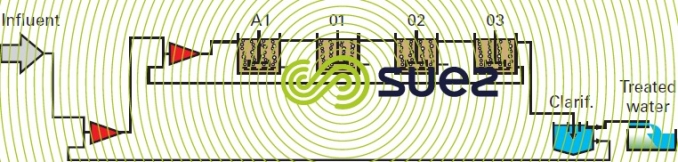
N/DN plan with pre-anoxic zone
In this case, the plant comprises (figure 27):
- a complete mix anoxic tank;
- a plug flow aeration tank simulated by three complete mix zones in series.
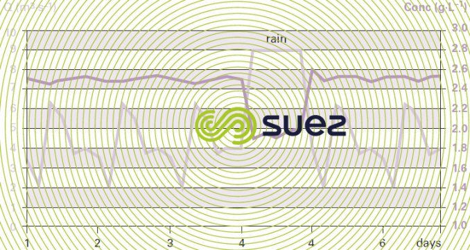
The example selected demonstrates the consequences of a rainfall episode (figure 28, 4th day) on the sludge concentration in the tanks. Additionally, it is used to determine the oxygen requirement distribution in each cell and the peak coefficient that has to be applied (figure 29).

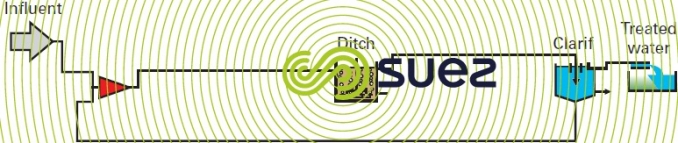
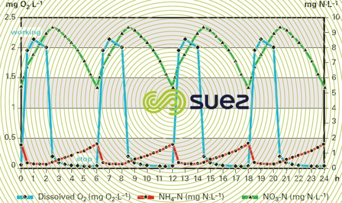
N/DN plant, sequenced channel configuration (figure 30)
The example models aeration syncopation in the channel. It shows (figure 31) the change in the dissolved oxygen concentration in the tanks and the repercussions on instant N-NO3 and N-NH4 levels in the discharge.
Note: only the modelling applications for activated sludge have been presented. Other processes can also be modelled.
Bookmark tool
Click on the bookmark tool, highlight the last read paragraph to continue your reading later
