


selecting ozonation reactors
Reading time:As detailed in the oxidants and disinfectants, can react through the molecular mode (the active oxidant is ozone) and/or through the radical mode (the active oxidant is the hydroxyl radical created by the breakdown of ozone) depending on the composition of the medium into which it is transferred. This reaction can alter ozone transfer.
kinetic aspect – hydraulic of the reactor
Selecting the best reactor for oxidation depends on the reactions occurring. In general, the rate at which ozone reacts with mineral and organic compounds as well as micro-organisms is modeled through a second order equation with partial orders of 1 for each of the reactants :


where: K is the reaction rate constant, n is the stoichiometric coefficient, [M] ([O3]) is the concentration of compound M (in the dissolved ozone), and rM (rO3) is the rate at which compound M disappears (the rate at which dissolved ozone is consumed).
The values for rate constants k vary considerably depending on the extent to which compounds M react with the ozone. The section the oxidants and disinfectants provides some qualitative indications.
Given partial order 1, a reactor where the liquid phase is subject to plug-flow conditions will always be more efficient than a completely mixed reactor. Therefore, ozonation reactors should be designed such that the liquid phase hydrodynamic is as close as possible to a plug-flow.
criteria to select ozonation reactors
The Hatta parameter (Ha), an adimensional number, is used to characterise the oxidation reaction and subsequently to provide guidance in selecting a gas – liquid reactor. Refer to table 8. E.g.:
- a very low Hatta number means that the transfer capacity of the liquid film is high as compared to the consumption rate of ozone: this is the chemical regime;
- conversely, when Ha is high, the ozone consumption rate may be much greater that the flux of ozone transferred: this is the diffusion regime.
For an irreversible order 2 reaction, the Hatta number is as follows:

The flux of ozone transferred according to equation (1) becomes :

where E represents the transfer acceleration factor caused by the liquid phase reaction, which is related to the Hatta number.
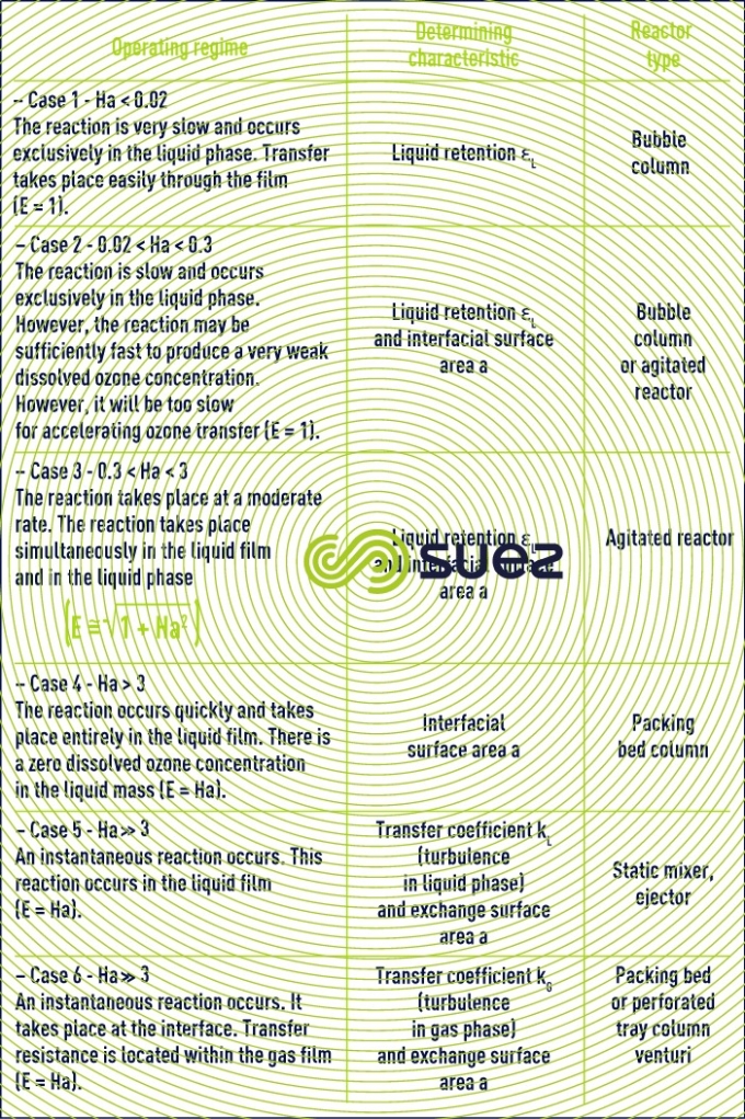

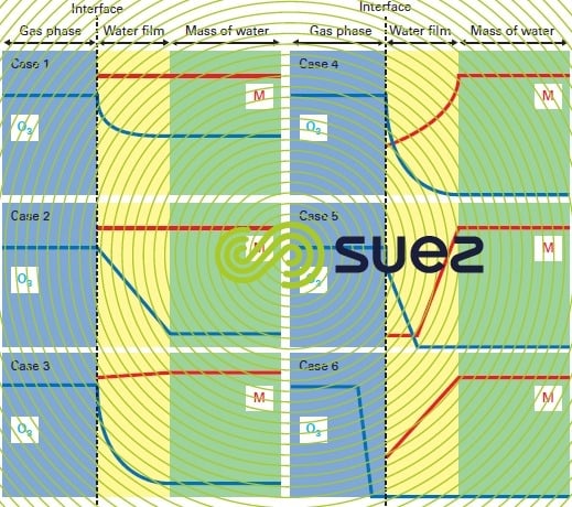
Figure 15 represents the concentration profiles in the vicinity of the interface for the various cases featured in table 8, based on the twin film model.
ozonation reactors
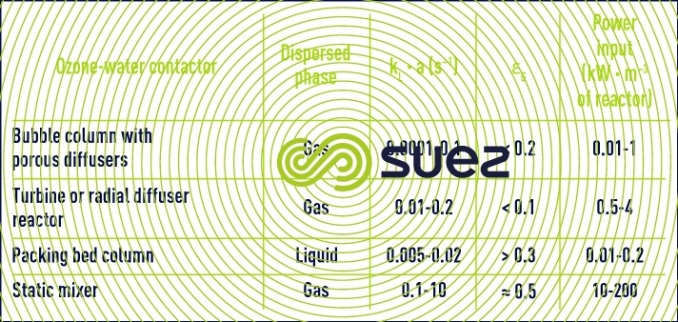
The main ozone-water contactors are detailed below based on the classification featured in table 8.
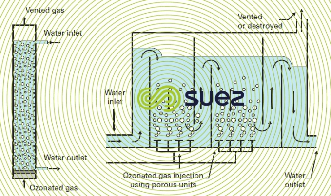
bubble column and ozonation chamber equipped with porous diffusers
The bubble column is the most common classic contactor for ozonation in water treatment applications. This type of reactor is available in two forms: the conventional bubble column and the ozonation chamber with multiple compartments in series. These reactors are depicted in figure 16. In these reactors, gas bubbles measuring approximately 3 millimetres in diameter are created by the porous diffusers located at the base of the reactor so that the gas can be distributed over the entire section of the column (photo 10). Gas and water flow concurrently via introduction of the water at the top of the column or by using baffles to properly direct the water in each compartment of the chamber. In this type of reactor, the water depth is 5 to 7 m above the diffusers. The number of compartments (usually 2 or 3) is adjusted according to the rate of chemical reaction and the distribution of ozonated gas flow set to reach the proper level of reaction completion (see also figure 26).
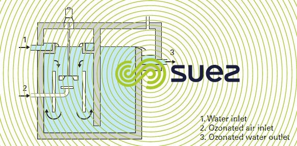
reactor equipped with a turbine or an axial diffuser
This type of reactor is used to homogenise the mixture in the contact zone by dispersing the gas throughout the liquid.
This mixture can be produced by :
- a radial propeller turbine that pumps the untreated water and directs it near the stream of ozonated gas shearing the gas bubbles at the same time (figure 17);
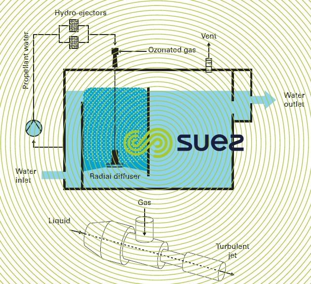
- a radial diffuser that expels a turbulent jet of ozonated gas – water mixture produced by an hydro-ejector (figure 18). In an hydro-ejector the gas is vacuumed, carried and dispersed into the recycled water due to a pump under the negative pressure created as the liquid vein contracts. This second mixing alternative provides a better ozone transfer as the ozonated gas is simultaneously dispersed and mixed with the untreated water inside the hydro-ejector.
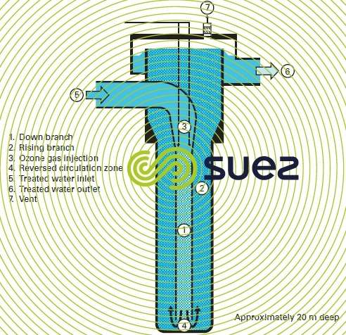
U tube
The U tube consists of two vertical concentric tubes that communicate at the bottom (figure 19). The ozonated gas is carried and dispersed with the untreated water, which is injected downward inside the inner tube by means of a highspeed (approximately 1.7 m·s–1 ). The maximum permissible ratio between gas and liquid flow rates is 0.17. In the inner tube, the water velocity and the increasing pressure generate small bubbles. The emulsion created then rises up in the annular compartment. Hydrostatic pressure and gas bubble contact time are important because of the water depth that is equal to approximately 20 m. This setup enhances ozone transfer.
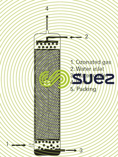
packing bed column
In this type pf reactor, the water to be treated is sprayed back against the flow of the ozonated gas (figure 20). The object of the packing bed housed in the reactor vessel is to distribute the liquid as a film and droplets while it is gravity flowing. Wetting the packing bed components increases the gas-liquid exchange area.
The packing material can be installed loose or in a structured form. Packing may be made of stainless steel or ceramics. The packing bed should provide the highest possible area per unit of volume for the lowest possible head loss.
.
static mixers
A static mixer consists of a tube fitted with fixed components that are used to mix the gas and liquid phases by repeatedly splitting the flow stream. The static mixer is mounted in a pipe at the discharge of a pump that flows water through at a velocity between 0.5 and 1.7 m · s–1. Ozonated gas is injected through nozzles upstream of the flow. The static mixer creates bubbles measuring approximately one millimetre in diameter therefore resulting in an extensive exchange area. The main feature of static mixers is their head loss that determines the power dissipated and accordingly the size of the bubbles.
The bubble size varies according to the flow rate for each fluid and to the type and number of components making the mixer. Pressure can vary from 0.05 to 0.3 bar per static mixer metre of length. A static mixer is used to inject gas into the contactor inlet similarly to the hydro-ejector, however it also transfers ozone into the liquid phase. A typical static mixer system comprises of a first mixer connected in by-pass for dispersing the ozonated gas and a main static mixer to transfer ozone into the liquid phase (figure 21). Depending on maximum head loss, the secondary static mixer will be replaced by an hydro-ejector. As a rule, the installation will require a downstream degasifying column for phase separation purposes.
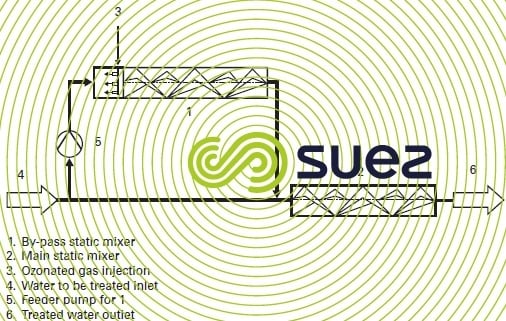
Table 9 provides a comparison of the performance criteria for the main ozonization reactors described.
For each application, the choice of the reactor is dictated by the process's determining factor which is :
- contact time for slow reactions;
- hydrodynamics for fast and moderately fast reactions (the target in these cases is a plug-flow hydrodynamic);
- ozone transfer for extremely fast reactions (the most appropriate contactors are those that have an extensive interface surface area).
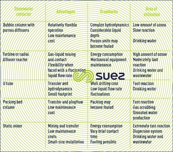
Table 10 summarises the technical advantages, drawbacks and scope of application associated with each of the reactors.
Bookmark tool
Click on the bookmark tool, highlight the last read paragraph to continue your reading later
