


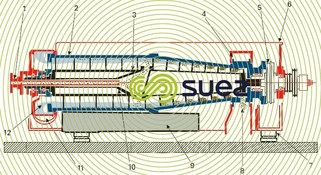
continuous cylindro-conical decanter
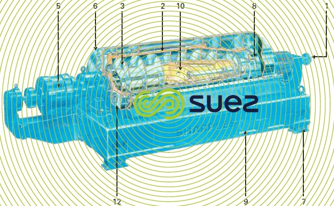
Reading time:Figure 30 provides a schematic diagram and figure 31 a cutaway view of a centrifuge.
The suspension to be processed is first flocculated before being injected into the machine through a fixed pipe (1) that opens out into a rotating distributor (10). This distributor spreads the sludge onto the periphery and propels the suspension into the annular space between the bowl (2) and screw (3). By the effect of the centrifugal force, the heavy particles settle and are deposited on the bowl’s inner wall. They are scraped off by the conveyor screw and routed continuously towards the conical section.A speed reduction gear (5) causes the screw to rotate slightly faster than the bowl (differential speed). The sediment compacted inside the cone is extracted through nozzles (8) distributed throughout the 360° of the cone point and recovered in the sediment casing (4).
The continuous feed pushes the discharging liquid towards the effluent sump (11) via adjustable weirs (12). Therefore, a liquid level becomes established in the machine, following the cylindrical surface (internal surface of the pool depth).
The entire machine rests on a ballasted frame (9) which itself rests on the ground via strong shock absorbers (7).
A protective casing (6) provides protection against the bowl’s high rotational speed.
In most cases, the materials used are either 304 or 316L stainless steel or Duplex steel.

Bookmark tool
Click on the bookmark tool, highlight the last read paragraph to continue your reading later
