


static thickener
Reading time:description (figure 5 and photo 2)
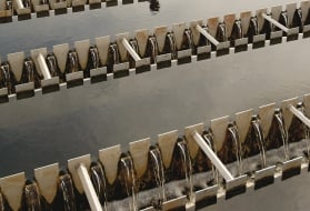
The thickener is a circular unit. The sludge suspension is introduced into the centre, inside the centre well. Matter settles according to its respective weight and forms a concentrated sludge blanket in the lower section of the structure.
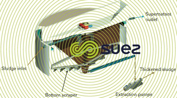


The normal residence time for sludge is approximately 24 hours. Thickened sludge is removed at the bottom, in the centre. The supernatant liquid is removed over a weir in the upper section. A rotating mechanical unit (scraper bridge) is used to:
- transfer the sludge that has been deposited towards to centre pit using scraper blades that are arranged in «louvers» over the sloping floor;
- facilitate the release of interstitial water and occluded gases by means of a vertical picket fence attached to the rotating mechanism (with some sludge, this picket fence is not always essential because the bridge structure is capable of carrying out this task).
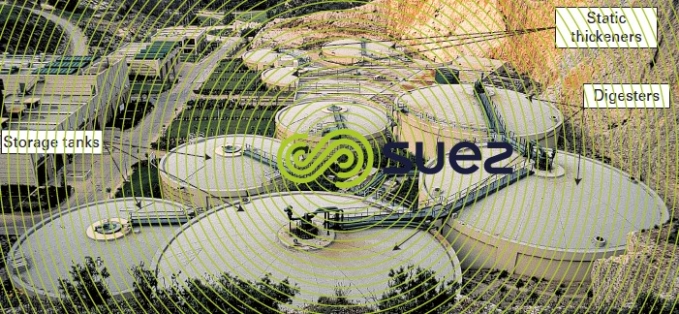
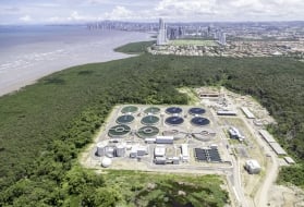
With fermentable organic sludge (e.g. case of WWTP primary sludge), structures are covered over and ventilated towards an odour control system (photo 3).
design
The Kynch theory is used to calculate static thicknener and, in particular, to determine the surface area applicable to the extraction concentration (see Coagulation-floculation).
The straight height (3.5 m minimum) must take several factors into account:
- target storage times;
- interstitial liquid clarification zone (minimum 1 m);
- operating conditions based on incoming flow and extractions and, therefore, on the dewatering operation.
In most cases, static thickening is used without polymer on organic sludge, such as WWTP sludge. Only injection of lime can be of benefit when fermentable sludge remains in a unit for a long time (e.g. over the weekend without dewatering) or in hot regions. The aim then consists in maintaining a pH of 7 to 8 in the bottom of the unit. This requires lime to be added at the rate of 10 % of the suspended solids in order to control fermentation and olfactory harmful effect.
On the other hand, with hydroxide sludge (e.g. drinking water sludge), polymer flocculation can be of considerable interest in order significantly increase the flow rates tolerated by the thickener.
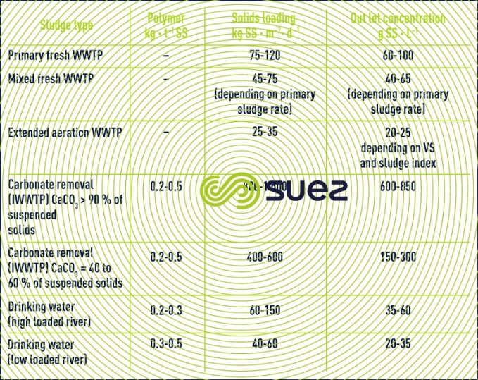
Table 1 provides a few design data applicable to the different types of sludge.
In WWTP, the static thickener is mainly applied on primary sludge. Recyling excess biological sludge to the primary settling tank inlet is becoming increasingly rare and, therefore, there are fewer and fewer mixed sludge applications (separate routing of primary sludge and biological sludge immediately upstream from the static thickener must be prohibited: the thickener is not a homogenisation tank and stratification will inevitably occur in the sludge blanket, resulting in variable sludge quality and concentration that will have a major adverse effect on downstream dewatering).
Static thickener performance on biological sludge remains rather disappointing, explaining the popularity of dynamic thickening for use with this sludge.
setting up
Classic mechanized thickener diameters range from 7 to 30 m. Concrete structure floors have a slope of approximately 15%; however this figure may be exceeded when heavy hydrophobic sludge is involved.
A centrally driven, twin diametric arm scraper is used.Appropriate drive torques are applied:60-80 m.daN · m–2 for dense mineral sludge and 20-30 m.daN · m–2 for WWTP sludge.Scraper velocities will vary from a few cm.s–1 to 15-20 cm.s–1 on the periphery:when the sludge is heavy and tends to compact very fast (e.g., carbonate removal sludge), high velocities are applied.
Thickening tanks are usually built of concrete but can also be made of steel (especially vitrified steel).
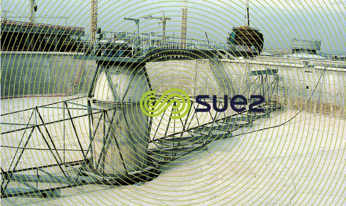
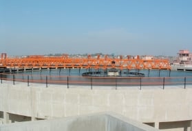
Note: 50-60 m structures are feasible (photo 4) except in very hot regions.
In working conditions, a static thickener is simple to operate but a few checks are compulsory: checking blanket depth (manually or using a probe), checking overflows (usually 150 to 500 mg suspended solids · L–1), checking thickened sludge concentration. This procedure allows us to remain in control of the structure’s buffer capacity in respect of the downstream system while avoiding fermentation that could cause problems. Once these checks have been completed, this process can run unmanned.
Its energy consumption is the lowest for the entire sludge system: 5-10 kWh · t–1 suspended solids. Stratification is often inevitable in IWW or drinking water plants processing variable density sludge.We then recommend using a preliminary homogenisation tank upstream from the thickener (polymer injection and concentrated sludge return) as well as continuous recycling within the thickener itself, at least during the periods when dewatering does not take place.
high loaded static thickener
In some cases, it is not advisable to look for a high level of thickening (e.g. direct dewatering using centrifugation, in order to reduce machine size - see high pressure centrifuges). Dimensioning is then calculated with reference to the first part of the Kynch curves, non-hindered settling phase.
This thickener pumps sludge out of the biological tank (2-5 g suspended solids · L–1) into which the overflow is immediately returned. As we have a very stable concentration at the inlet, this type of unit is very easy to stabilise.
Polymer conditioning (1 to 3 kg AM · t–1 suspended solids) must be carried out. For extended aeration sludge (N/DN) with simultaneous phosphorus removal (FeCℓ3), extraction concentration will vary between 10 and 15 g suspended solids · L–1.
filter or biofilter wash water thickening
This pre-homogenised effluent is very dilute (0.15 to 0.8 g suspended solids · L–1). Therefore, even faster settling tanks are required: in this case, Densadeg settling tanks.
Hydraulic loading of approximately 15 to 25 m · h–1 calculated on lamella surface area, is applied. Clearly, we need to use extremely high molecular weight polymer (and also, in general, FeCℓ3 for boosting coagulation).
Resulting sludge concentration ranges from 20 to 40 g suspended solids · L–1.

Bookmark tool
Click on the bookmark tool, highlight the last read paragraph to continue your reading later
