


dynamic thickening
Reading time:Dynamic thickening is mainly used on lightweight, hydrophilic sludge: biological sludge and hydroxide sludge. Its main properties are the speed of the process and dynamic thickening ability to achieve good concentration performances on problematic sludge.
The accelerated dynamic thickening of biological sludge is used to:
- eliminate the large static thickeners which, with this type of sludge, are modestly efficient and the source of loaded returns to the plant inlet (COD, phosphorus, nitrogen...);
- achieve a far greater degree of thickening, thus reducing the size of downstream systems;
- thicken fast, thus allowing the freshest possible sludge to be processed in the downstream system (and that is always a profitable matter) and not returning pollution to the plant inlet (in particular, no random discharge of phosphorus because the process does not include any anaerobic zone and no carbonaceous pollution due to the fact that there is little or no fermentation).
flotation
Dissolved air flotation is the main system used for sludge thickening. Please refer to microbubble flotation ( DAF or FAD ) ( DAF or FAD ) for the principle of dissolved air flotation.
The most widely used flotation units are circular because they perform better in thickening applications: indeed, due to the flotation unit design, the bubble bed covers the entire surface of the unit. Furthermore, the sludge blanket is thicker, evenly spread and, consequently, floated sludge concentration is higher.
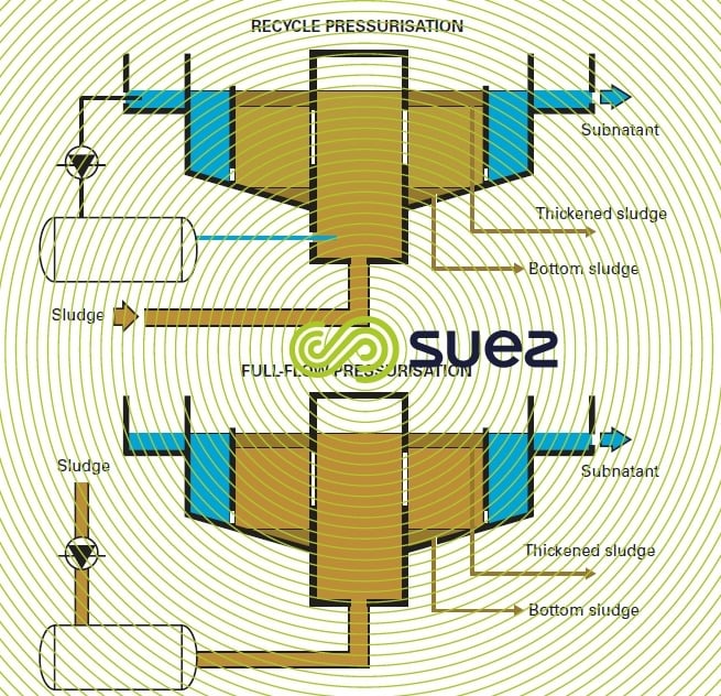
Full flow or recycle pressurisation (figure 6) can be used. In the full flow process, the sludge itself is pressurized. The pressurisation and pressure relief system have been designed to cope with elements carried in the sludge without imposing any operating restrictions (use of self-cleaning pressure relief valves).
The full flow process has many advantages:
- higher dry solids content for floated sludge (+ 5 to 10 g suspended solids · L–1);
- requires no polymer when processing biological sludge regardless of its quality (SVI, VS);
- high solids loading (approximately 100 kg suspended solids · m–2 · d–1);
- no setting adjustment required while operating even with a variable quality or concentration infeed;
- acceptable subnatant (80 to 200 mg · L–1);
- very few bottom sludge.
In the recycle pressurisation process, the water is pressurized (usually the subnatant from the flotation unit) and then depressurised and mixed with the particles at the flotation unit inlet. The pressurised water flow frequently represents more than 80 % of that of the sludge to be floated. When used in biological sludge thickening, the recycle process is subject to a few limitations:
- floated sludge concentration is not so high;
- when processing problematic biological sludge (high VS content, fairly high SVI), polymers are often required to assist clarification and prevent the accumulation of bottom sludge;
- the recycling rate has to be adjusted when sludge concentration or quality varies. Obviously, there is a solution: the use of high recycling flows as a safety measure (150-200%) but this will be to the detriment of energy consumption levels;
- on the other hand, we will have a better quality subnatant (50-100 mg suspended solids · L–1).

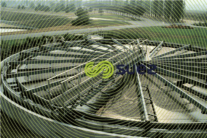
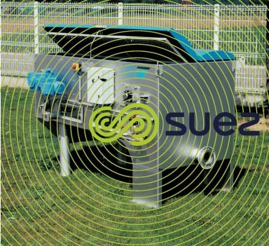
description of the full flow pressurisation flotation unit (photo 5 and figure 7)
Sludge to be floated arrives at (1), at the pressurisation pump intake (9). A mixed intermediate tank (7) uses level detection to ensure that the flotation unit adjusts to the variable flow rates arriving at (1). Sludge to be floated is then routed to the air saturation tank (10) that is fed with a supply of regulated compressed air (11). A constant level is maintained in this air saturation tank. The pressurised sludge (4 to 5 bar) is depressurised in a dual expansion system (3).The first pressure relief valve (A) produces the first pressure break, the 2nd diaphragm valve (B) is self-cleaning and produces the final depressurisation by creating appropriate micro bubbles (50-100 mm).Two pressure release circuits (each connected to a dedicated pressurization pump) are used to adjust the output to the flotation cell according to changes in inlet tank level (7).
The sludge is then routed into the expansion chamber (2).
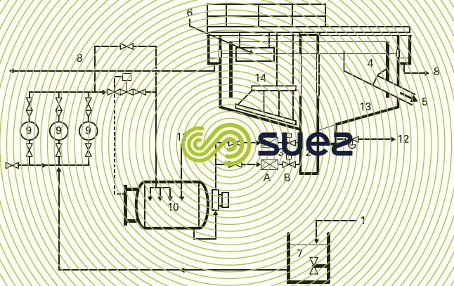
Made lighter by the micro bubbles, the floc concentrates on the surface. A scraper system (6) draws the sludge towards the collection channel (4). The sludge is then removed (5) to a degasifying tank (a large number of slow moving skimmer blades (photo 7) are used in order to avoid excessively powerful energy disruption on the surface).
The clarified water is removed (8) after passing beneath a scum baffle (13). Bottom sludge (if necessary) is scraped using a small scraper (14) and removed at regular intervals (12). This effluent is returned to the plant inlet.
performances achieved with biological sludge (full-flow pressurisation)
The following dimensioning bases are the result of operating feedback from over two hundred plants:
- thickening without polymer;
- systematic inclusion of a self-cleaning diaphragm valve (sequenced opening);
- with extended aeration sludge (no primary settling):
- loading :4 to 6 kg suspended solids · m–2 · h–1;
- when SVI < 150 :floated sludge 4.5-5.5 % DS ;
- when SVI 150-250 :floated sludge 4-4.5 % DS ;
- when SVI > 250 :floated sludge 3.5-4 % DS
- with biological sludge (and primary settling):
- loading : 3.5 to 4.5 kg suspended solids ·m–2 ·h–1;
- when SVI < 100 : floated sludge 4-4.5 % DM ;
- when SVI 100-200: floated sludge 3.5-4 % DM ;
- when SVI 200-300: floated sludge 3-3.5 % DM ;
- when SVI > 300 : floated sludge < 3 % DM
In this application, the rising velocity is less than 2 m·h–1. Infeed concentrations of less than 6 g suspended solids · L–1 are recommended in order to ensure adequate pressurisation (extraction can take place at choice from the biological tank or from settling tank recycling).
performances on hydroxide sludge (e.g. drinking water plant)
The use of polymer is compulsory in this case. Therefore, recycle pressurisation becomes quite applicable again and may be selected. Floated sludge concentration will have approximately 25-30 g suspended solids · L–1 and velocities in the region of 3-4 m · h–1 on this sludge which is frequently diluted (1 to 2 g suspended solids · L–1).
performance on filter or biofilter wash water
This sludge is extremely diluted and can also be thickened using the flotation process. In this case, we come close to flotation of rather loaded water. Therefore, reagents will be required: polymer at the rate of 2 to 4 kg AM · t–1 suspended solids and, if sludge is rather diluted (150-400 mg suspended solids · L–1), coagulation using FeCℓ3 will often be required. Polymer is injected in-line. Recycle pressurisation (20-30 % of recycled volume) tends to perform better because we have to achieve a thoroughly clarified subnatant (15 to 80 mg suspended solids · L–1).
The relevant hydraulic loading will range from approximately 3 to 10 m · h–1 (depending on the type of washing water) and target concentrations from 25 to 40 g suspended solids · L–1.
setting up full flow pressurisation flotation units
In general, flotation units, which tend to be large because they become competitive as soon as the plant increases in size, are constructed of concrete or steel. To date, we have remained within the 20 m diameter flotation unit limit as this is enough to treat biological sludge from a plant that services approximately 500 000 p.e.
A flotation unit operates continuously, unmanned (the sludge blanket depth is checked once daily).Sludge extraction (skimming) can be automated (surface sludge blanket depth sensor, a blanket that is between 30 and 60 cm thick).
Approximately 1 to 2% air on suspended solids is consumed.
Energy consumption remains high:60-120 kWh·t–1 suspended solids (compared with static thickeners or draining units) but it is offset by the process’s high level of flexibility and reliability, achieved, in most cases, without any polymer.
In general, no standby units are required for this type of installation (except pumps). Indeed, loading can always be increased momentarily in a flotation unit (peaks, malfunctions, delays to be made up…).Polymer then has to be used in order to achieve a «high loading flotation» (polymer injected in-line). We then have the following performances for extended aeration sludge
- polymer:2 kg·t–1 suspended solids,6 to 8 kg suspended solids·m–2·h–1 loading;
- polymer:3 kg·t–1 suspended solids, 7 to 9 kg suspended solids·m–2·h–1 loading;
- polymer:5 kg·t–1 suspended solids, 20 to 40 kg suspended solids·m–2·h–1 loading;
Concentrations only see a marginal increase whereas, on the other hand, the subnatant becomes lightly loaded:30- 50 mg suspended solids·L–1.
Due to the oxygen that is injected and the brief contact time, a flotation unit creates few or no nuisance, particularly when it is operating continuously.Nevertheless, the sludge is «visible» and, accordingly, many structures are now covered over and ventilated.
drainage
In small and medium size waste water treatment plants, thickening technologies based on drainage are often prioritised. These units are compact and easily operated but they do require the formation of a voluminous, well separated floc and, therefore, relatively high amounts of polymer.
The concentrations achieved are higher than those provided by a flotation unit and energy consumption is lower (25-50 kWh · t–1 suspended solids)
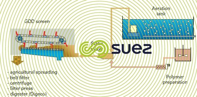
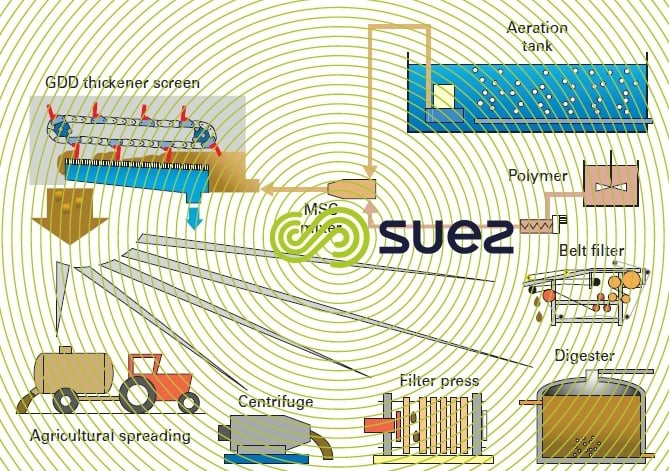
GDD/GDE screens (figures 8 and 9)
description
This is the appliance of choice for processing diluted biological sludge.
Sludge (1) is first flocculated (MSC static cyclonic flocculator for small units and a mechanical flocculator for the larger appliances) and then applied over a horizontal fine screen rack (2). The special shape of the screen bars and the gap separating these (350 to 800 mm) will ensure that the interstitial released water drains off rapidly. The floc remains on the screen where it is gradually thickened and routed to the outlet (6) by rubber scraper blades (4), driven by a chain assembly (3). Filtrate is collected (5) in a closed box positioned beneath the screen.
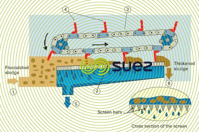
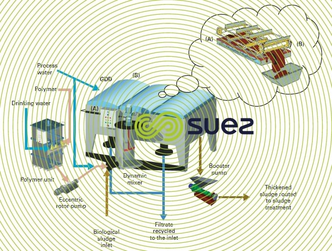
The screen unit is enclosed in a housing. The screen is washed at regular intervals by a sprayer equipped with jets that travels in the rack beneath the screen. The overall screen unit is thus washed without interrupting the appliance’s operation.
advantages
GDD/GDE screens present the following main advantages:
- continuous, unsupervised operation;
- an extremely compact, wholly enclosed appliance that allows nuisances to be kept under control (completely hooded over with ventilation conveying odours to the odour control unit).All components are constructed of stainless steel or plastic in order to limit corrosion;
- the filter medium (screen) is fixed. Therefore, there are no moving belts and no restrictions in terms of centering and lateral movement:
- the GDD screen (figure 10) (350 and 600 mm twin mesh) can be used to process very dilute sludge (2 g suspended solids · L–1 possible). This constitutes a major advantage because it allows sludge to be drawn direct out of the biological tank, regardless of the sludge concentration.
Therefore, there is an extremely homogenous concentration at the unit’s inlet. This enables us to achieve optimum polymer adjustment and reliable, unmanned operation (clearly, this does not apply when the drawing off is made from the clarifier’s recycling cell because, then, the concentration will vary according to the flow entering into this clarifier and to top layer of sludge management). The GDD screen is used to rapidly thicken totally aerated sludge and, therefore, returns virtually no pollution (phosphorus, BOD5…) to the plant inlet. With this heavily diluted sludge, polymer is a reticulated emulsion used to create a floc that is sufficiently resistant and voluminous;
- the GDE screen (constant 600 or 800 mm mesh) is used for the most concentrated sludge.
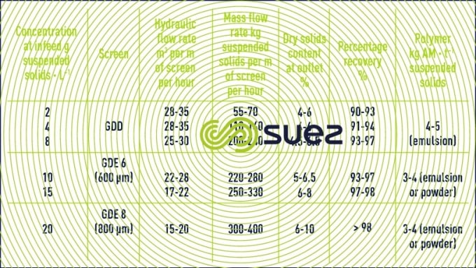
dimensioning
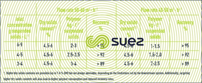
For WWTP biological sludge, the following bases need to be taken into account (table 2):
As there is no pressing and as washing takes place periodically, separation efficiency is high.
The GDD/GDE screen is used upstream from a dewatering unit (figure 11). It is not always advisable to aim at maximum thickening because this could make difficult to achieve flocculation, particularly upstream from centrifuges and even filter presses.
setting up (photo 6)
The range goes from 0.5 to 4 m wide (i.e. 10 to 140 m3 · h–1 of sludge). The screens can be placed at ground level with collection by booster pump or direct over the thickened sludge storage tank.
Wash water consumption will be reduced because a very moderate and, furthermore, intermittent flow is delivered by the sprayers. Dynamic thickening using GDD/GDE screens represents one of the most competitive investment costs.
gravity belt thickener (GBT) (figure 12)
Drainage is carried out through a moving belt (600-800 mm) similar to those used on belt filters (see belt filters).
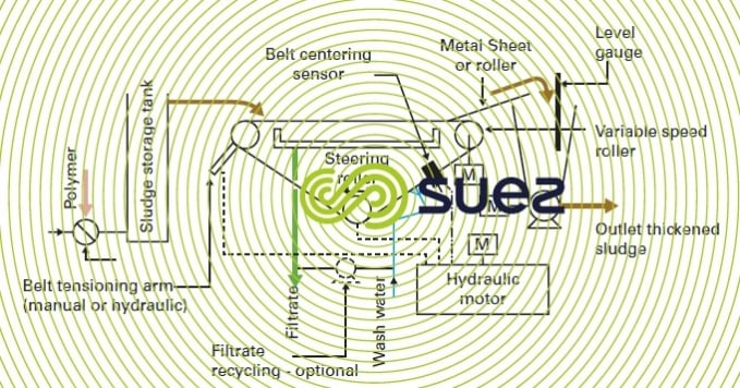
Therefore, belt centering and tensioning units are required. Washing takes place continuously (fairly high flow rates of 4-5 m3·m–1·h–1). Belt velocity is quite high: 10 to 20 m · min–1).
Therefore, hydraulic flow rates will be high: approximately 40 to 60 m³ per metre’s width per hour. Post-pressing is an option at the unit’s outlet.
However, this type of appliance is not so compact (quite long) and requires a little monitoring, especially regarding belt travel. Additionally, as a rule, this system requires sludge of more than 4-5 g suspended solids · L–1 for reliable operation. These appliances can also be equipped with a whole hood (which does not make it any easier when carrying out maintenance on the unit).
draining drum
These rotating drums are equipped with a filtering cylinder (usually a belt). These units have a relatively modest output (and are, therefore, better suited to small water treatment plants) and a resistant floc is required because, unlike screens and GBT, the rotating unit applies a certain amount of stress to flocculated sludge. Therefore, these drums tend to be used on thicker sludge (7-10 g suspended solids · L–1).
centrifugation
The centrifugation technology is described under the section centrifugation
This is the technique that produces higher levels of thickening merely by adjusting operating parameters.
In general, the centrifuges used are the same as those used for dewatering. Sometimes, however, some manufacturers offer more specific machines (e.g. a centrifuge with a lamellar zone for collecting centrates).
This process becomes wholly justified when feeding highly concentrated sludge into the stabilization stages.
A (moderate) amount of polymer will be required in order to produce a light loading centrate (essential when the machines are being supplied with dilute sludge).We then have to aim for centrates having less than 500 mg suspended solids · L–1.
In thickening applications, the hydraulic flow rate, for the sizing, constitutes a limiting factor. Therefore, sludge must be extracted from the clarifier's recycling pit in order to obtain concentrations of at least 7-8 g suspended solids · L–1 at the machine's inlet. Consequently, homogenous concentration is not guaranteed and the process will be very sensitive to changes in sludge properties. In order to make this a reliable process, we need to install a preliminary homogenisation tank or an appropriate automated control system (e.g. regulating the screw’s differential velocity by measuring thickened sludge concentration in order to guarantee stable concentrations at the unit’s outlet).
As the machines operate with a high hydraulic flow for a relatively low mass load, these units have the highest energy consumption levels of all thickening appliances: 120 to 200 kWh · t–1 suspended solids.
For example, for WWTP biological sludge, table 3 provides some performance figures for a machine having a ∅ 500-550 mm diameter bowl and an LT/∅ ratio of more than 4 (sludge with SVI< 150 and less than 75 % of VS).
Thickening through centrifugation is normally used in relatively large WWTP and when space is at a premium; indeed, this is a relatively compact process that does not generate olfactory nuisances.
For details of the operation of these machines, please refer to centrifugation. However, in thickening mode, the main operating parameters are those detailed below:
- operation at a high VR (15 to 30 rpm);
- low torque and, therefore, the need for alternative automation systems for stable operation; inlet mass flow can be measured so that the amount of polymer can be adjusted, VR or pool depth can be regulated according to thickened sludge concentration, centrate clarification can be checked...
- higher bowl velocities not sought systematically;
- precise pool depth adjustment, usually slightly negative.
When centrifugation is used for dewatering, using identical machines for thickening will undoubtedly be advantageous as far as operations are concerned: possible use as standby units, spare part harmonisation…

Bookmark tool
Click on the bookmark tool, highlight the last read paragraph to continue your reading later
