


conventional recessed plate filter press
Reading time:Pressure filtration takes place in closed chambers. Unlike the belt filter system, sludge is compelled to undergo the stress applied (creep is not possible).
This relatively old technique is still widely used. Its major advantage, one that is often the basis for decisions, is the production of a cake qualified as «solid» and, therefore, usually containing over 30 % DM (thus, the highest dry solids content for mechanical dewatering).Nevertheless, its drawbacks are significant:
- intermittent type operation (successive batches termed cycles);
- feed flow rate declines along the entire cycle;
- higher investment costs than other mechanical dewatering units;
- mechanized discharge between each cycle but with inevitable manual assistance to ensure the cakes drop off (in any event, this applies to most sludges).
However, some progress has been achieved over recent years:
- polymer treatment has become reliable, dispensing with the need for lime;
- some automatic filters have been developed but no problematic mechanical working and reliable operation have yet to be confirmed for all types of sludge and especially problematic hydrophilic sludge.
general description of a conventional recessed plate filter press (figure 40)
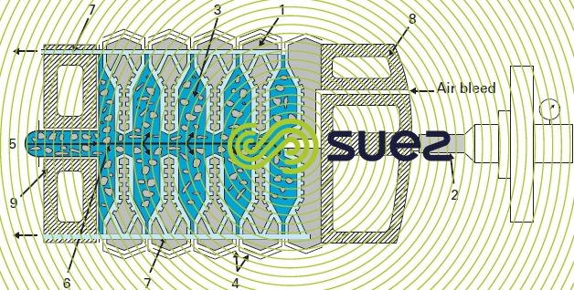

A filter consists of an array of vertical, recessedplates (1) that are juxtaposed and held firmly together by a moving head (8) actuated by one or more hydraulic cylinders (2) positioned at one end of the array. The thrust developed by the moving head/plates assembly is contained by a fixed head (9) positioned at the other end.
This vertical plate arrangement forms closed filtration chambers (3), and facilitate the use of mechanised means for dropping off the cakes («discharging»).
Fairly small mesh (10 to 300 mm) filter cloths (4) are placed on the two grooved sides of the plates.
The sludge to be filtered (5) is pumped into the filtration chambers through openings (6) that are usually located in the centre of the plates; the alignment formed by these holes constitutes the sludge feed pipe.
Solid matters gradually accumulates in the filtration chamber until the final compacted cake is formed.
The filtrate is collected in the grooves of the plate, behind the filter cloths, and removed through internal pipes (7) (therefore, without any external nuisance).
The pressure generated by the clamping cylinder(s) must be calculated so that the sealing pressure applied on the joint face of each filter plate exceeds the chamber’s internal pressure developed by the sludge pumping system
technologies applied
Their main difference is as follows:
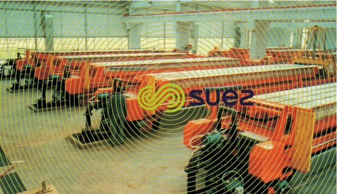
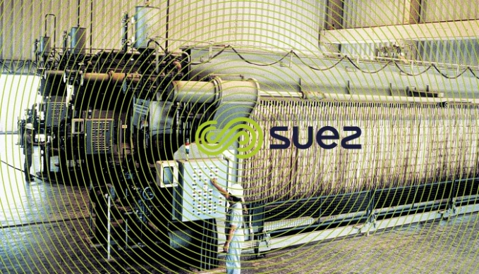
- filter plate supports : either lateral on two lengthwise bars (photo 22) or hooked over one or two overhead rails (photo 23);
- individual plate separation system (electro-mechanical or hydro-mechanical (photo 24):
- the closing system: one or more hydraulic cylinders;
- the belt high pressure wash system.80-100 bar pressure is required to wash belts and grooves using wash sprayers that are not too far from the belts to ensure that the pressure remains effective;
- safety margins applied to support structure design;
- appliance size: from small filters (20 to 30 plates measuring 500 × 500) to larger filters (150 to 160 trays measuring 2,000 × 2,000 i.e. overall capacities of 15,000 to 18,000 litres and over 1 000 m2 of filter surface area in relation to a floor space of approximately 40 m², therefore quite compact;
- pressure applies: 15 bar as standard but, for some sludge, 7 bar (less expensive) versions are available from some suppliers;
- cake thickness: chamber depth and, therefore, final cake thickness must be selected according to the nature of the sludge. Very good filterability, dense sludge produces a considerable thickness (50 mm) thus avoiding excessively short cycles that are penalising. For most urban sludge, 30 mm will be the recommended thickness, constituting a satisfactory compromise between cycle time and cake weight;
- plate technology: polypropylene is now in widespread use (the larger units are still equipped sometimes with cast iron plates).Each plate has a number of evenly distributed bosses. These bosses prevent the internal section of the filter plates from distorting should the filter press be incorrectly filled;
- filter cloths: in most applications, these are cloths woven from synthetic fibres, single filament (polypropylene or polyamide-Rilsan). In most cases, the cloths will be fitted over a coarser under-cloths (better filtrate removal and less stress on the fine filtration cloths).
Multi-filament, closer textured cloths are used for very fine hydroxide sludge.
In a well-operated unit, cloths will have a working life in excess of 2000 cycles.
filtration cycle
The filter press works using a series of pressings. Each pressing comprises the following phases:
- press closes: asthe filter is completely empty, the mobile head, actuated by the cylinder(s), clamps the plates together. The clamping pressure is automatically adjusted throughout the filtration in order to ensure that the joint faces are sealed;
- the filter is filled: this is a short phase (maximum of ten minutes). A feed pump fills the filtration chambers with sludge for filtration. The filling time selected depends on sludge filterability (the better the sludge filterability, the shorter the fill time);
- filtration: once the chambers have been filled, the continuing arrival of sludge results in a pressure risep caused by the formation of an increasingly deep layer of sludge on the filter cloths. Maximum filtration pressure is often reached within 30 to 45 minutes. Filtration can take from 1 to 5 hours depending on chamber depth and on sludge filterability. The filtration phase is usually ended by a timer (programmed period during which maximum pressure is maintained) with a view to obtaining a final filtrate output of 5 to 10 L · m–2 of filtering surface area and per hour when using polymer conditioning and 10 to 20 L · m–2·h–1 when using mineral conditioning. When the filtration pump is shut down, compressed air is used to drain out internal liquid sludge and filtrate circuits;
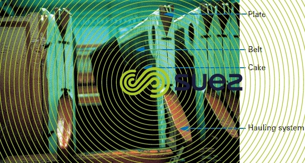
- frame opening: the mobile head is withdrawn so that the first filtration chamber opens. The cake that has formed drops under its own weight. A mechanised system then pulls each plate individually. Depending on the extent to which the cake adheres to the cloths, it will take between 15 to 45 minutes to disharge the cakes on a filter that has approximately one hundred chambers. This phase must be supervised because many sludge types, subject to inadequate conditioning or to polymer conditioning, will deliver cakes that are more or less sticky and a rake then has to be used to ensure that they are completely detached.
In addition to these four filtration cycle phases, there is the extremely important cleaning phase: cleaning the cloths and behind the filtrate discharge grooves. This wash is carried out every 10-15 cycles when polymer conditioning is used and every 30-40 cycles in the case of mineral conditioning. Washers (photo 16) can operate unmanned on the larger units. Washers are synchronised on plate hauling. A wash takes approximately 2-3 hours. When massive lime conditioning is used, cloths and plates have to be descaled approximately every 500 cycles: usually by soaking or circulating a passivated HCℓ solution having a 5-7 % tilrated.
The filter press consumes relatively few energy: approximately 25 to 35 kWh · t–1 suspended solids depending on sludge type.

filter press dimensioning
We need to know:
- the quantity of suspended solids (sludge + added conditioning reagents) to be filtered each working day = M;
- the overall cycle time = T (depends on cake thickness and on conditioned sludge specific resistance r0.5); cycle time T is used to decide the number K of cycles feasible per working day (depending on operation time);
- final average dry solids content of the filtration cake SF;
- cake density.
A filter press is dimensioned by the total capacity VT of its filtration chambers:


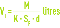
where:
M in kg suspended solids · d–1
SF as a fraction (= 100 SF as the %/ DS).
An economic compromise can then be reached between the number of cakes and the plate size range.
N.B. the filter press is the mechanical dewatering appliance that produces the best separation performance (approximately 98-99%).
performances achieved with mineral conditioning
Table 22 provides an overview of performances obtained with some hydrophobic sludges (no conditioning), a few mineral tendency hydrophilic sludges (conditioned using lime only) and a few organic tendency hydrophilic sludges (conditioned using both ferric salts and lime).
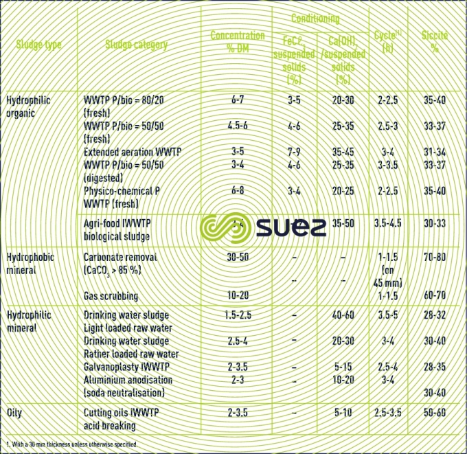
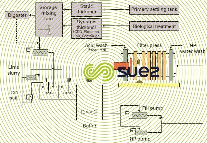
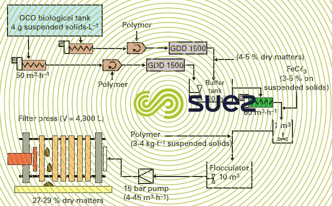
Figure 41 is a diagram of a filtration system representing the above application.
performances achieved with polymer conditioning
Polymer conditioning is an attractive option because there is no increase in waste tonnage (unlike mineral conditioning that often requires the addition of large amounts of lime).On the other hand, most sludge types produce a more or less sticky cake which increases frame opening time and manual assistance for detaching the cake.
Ferric chloride must be used in conjunction with polymer on organic sludge in order to reduce this adhesion.
In view of the fact there is no added mineral loading, dry solids contents obtained are certainly lower and the cake will have a spongier structure.
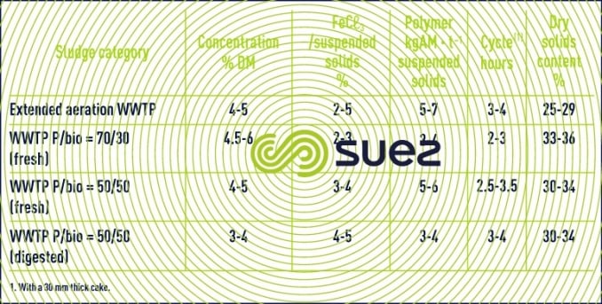
Table 23 provides some performance figures for sewage residual sludge.
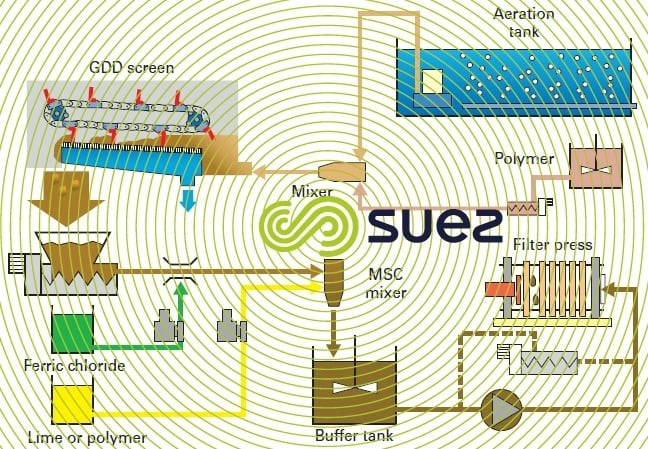
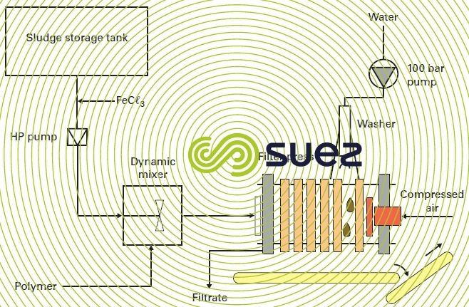
Figures 42, 43 and 44 provide several examples of the application of polymer conditioning in a filter-press unit.
Combined conditioning systems (mineral with lime or polymer – figure 42) are very interesting: in effect, lime treatment satisfies agricultural requirements in terms of final disposal. When this final disposal become impossible or poses problems, polymer conditioning allows the sludge to be routed to thermal drying or incineration while maintaining acceptable dry solids contents and, therefore, maximum net calorific value.
Bookmark tool
Click on the bookmark tool, highlight the last read paragraph to continue your reading later
