


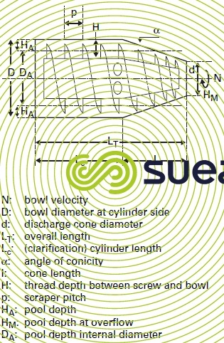
main geometric parameters
Reading time:A centrifuge is characterised on four main criteria:
- its hydraulic flow rate: number of m3 · h–1 of sludge it can accept;
- its mass flow rate: kg DM · h–1 (hydraulic flow rate × inlet sludge concentration);
- sediment dry solids content obtained in the sediment;
- its extraction performance or percentage recovery: quantity of DM in the sediment comapred to the total quantity of suspended solids at the inlet.

bowl diameter D and LT/D ratio
The diameter is characteristic of the machine ranges and will vary from 0.25 to 1.1 m in sludge treatment applications. The treated throughput treated increases with the diameter and the LT/D ratio and, as a rough guide, we can expect that:
- for an identical LT/D ratio, the flow rate extrapolation factor will be close to the D13/D23 ratio for two machines having D1 and D2 diameter bowls;
- for the same diameter, when the LT/D ratio increases from 4 to 5, depending to the sludge, we will improve the mass flow rate from 30 to 50 %.
angle of conicity
The angle of conicity usually ranges from 8 to 12° for all applications.
Narrower angles (6-7°) can be used to extract particularly problematic sediments (thixotropic textured, sticky sludge such as drinking water sludges or carbonate removal sludges).
Wider angles (20°) can be used to extract sediment that has a firm and compact texture: this produces a larger cake internal storage capacity and, therefore, a small increase in mass flow rate.
thread height H between screw and bowl
A wide space will allow sediment reisdence time in the machine to be increased and, therefore, prolonged centrifugal force action.
space separating the screw and the bowl in the conical section
The narrower this space, the higher the compression rate applied to the sediment. This is one of the key parameters in centrifuge development, increasing dry solids content and justifying the designation of HP (high pressure) centrifuge applied to the more efficient units available from different constructors.
clarification surface area S with a maximal pool depth
This important parameter establishes the maximal clarification surface area:


A machine’s flow rate Q will increase with the surface area.
bowl internal capacity
The bowl’s internal capacity ratio can also be used for a rough extrapolation of flow rates, providing that it is corrected for the various acceleration ratios (FC1/FC2) as follows:
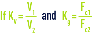
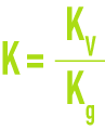
the flow rate extrapolation factor K becomes
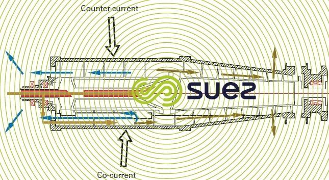
counter courant or co-current system
Figure 33 illustrates 2 principles. The co-current system (inlet at the beginning of the cylindrical section) still has its uses in certain cases where thickening takes place without polymer or with particularly problematic sludge (very light sediment); this system usually produces lower dry solids contents but good clarification.
At present, the most widely used, the counter current system produces higher dry solids contents with higher mass flow rates.
Additionally, versatile rotors are also available.
Σ Factor
This factor represents the single settling surface area equivalent to that of the centrifuge concerned operating at 1,000 g. Each manufacturer has his own method for calculating this Σ factor and, therefore, any comparisons must be conservative.
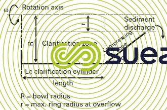
The following is a formula that can be used for a rough calculation of this parameter (see notations on figure 34):

In order to compare the machines with each other, Σ is calculated at nominal operating velocity N (developing a 1,000 g acceleration).
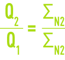
In principle, ΣN can be used to extrapolate the hydraulic capacity of machines from different ranges. However, it should be used with caution:
screw extractor
Screw thread height and pitch have a major impact on machine hydraulic capacities. The screw extractor is the unit that is the most sensitive to abrasion. The screw thread is always protected by powdered tungsten carbide of sintered tungsten carbide tiles.
Each manufacter offers specific features: openwork threads in the cylindrical section for faster transfers and less turbulence for the liquid, variable pitch in the conical section to improve compression rate, sludge fed in the cylindrical zone or at the cylindrical-conical break joint...
Bookmark tool
Click on the bookmark tool, highlight the last read paragraph to continue your reading later
