


anaerobic digestion
Reading time:Methane fermentation (see Anaerobic bacterial cultures) is one of the most powerful cell destroyers found in the biological world and is used to eliminate large quantities of OM. Anaerobic digestion of sludge is usually applied without recycling the thickened, digested sludge because the residence time and the sludge’s initial OM concentration allow to synthesise bacterial flora without any danger of leaching.
Gas output is the most representative and simple criterion for assessing the quality of the digestion. It mainly depends on three factors:
- temperature;
- residence time;
- the stabilisation level of the OM that undergoes digestion.
In UWW wastewater treatment plant, the object set usually consists in using digestion to achieve a 40 to 50 % reduction in the OM content of mixed sludge.
A properly balanced digestion system will produce 900 to 1,100 L of gas for each kg of OM destroyed. The gas mainly consists of CH4 (60 to 65 % v/v) and of CO2 (35 to 40 %v/v).Other elements may be present in very small amounts: CO, N2, hydrocarbons, H2S, mercaptans, VOC. Clearly, its net calorific value will depend on its proportion of CH4. This proportion will range from 21,300 to 23,400 kJ · Nm–3 (5,100 to 5,600 kCal · Nm–3).
Satisfactory digestion operation depends heavily on temperature: start-up speed, stable fermentation, gas production.
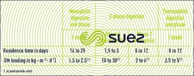
Mesophilic fermentation, around 35°C, is the process normally applied.
Thermophilic fermentation (50-60°C) is more rarely used: however, it does allow reactor capacity to be reduced by a factor of 2 and eliminates a far greater number of pathogenic germs but at the expense of a less favourable energy consumption.
Two-phase anaerobic digestion constitutes an excellent compromise:
- for achieving rapid OM hydrolysis in a first, brief residence time, thermophilic reactor;
- for optimising the methane fermentation phase in the second mesophilic reactor.
parameters affecting anaerobic digestion efficiency
In addition to temperature, residencetime (based on the daily incoming flow of fresh sludge) and the organic loading applied are essential dimensioning elements.


Where:
HRT: hydraulic residence time (days)
V: reactor capacity (m³)
Qs: fresh sludge flow rate (m3·d–1)
OL: organic loading (kg OM · m–3·d–1)
Cs: fresh sludge suspended solids concentration (g · L–1)
OMs: percentage OM/suspended sludge (%) of the fresh sludge.
A satisfactory residence time is obtained when:
- the reactor has the right capacity;
- there is a sufficiently strong concentration of fresh sludge, limiting the throughput to be processed.
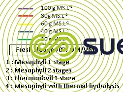
Figure 15 expresses OL variations as a function of the HRT and of Cs andalso identifies the areas within which the various types of anaerobic digester operate satisfactorily (see liquid sludge stabilisation).
Note: residence time can always be extended in order to avoid exceeding maximum loading levels (shown as the areas between dotted lines).

Three additional parameters enhance sludge digester operation and performance:
- mixing intensity, far more useful for (viscous) sludge fermentation than for effluent fermentation. Efficient mixing will reduce temperature and OM concentration variations within the digester mass and multiply opportunities for contact between micro-organisms and matter that has to be broken down. The difference that may be recorded between the digester performance in the laboratory on the one hand and the lower performance achieved in industrial digesters can often be explained by the difference in mixing intensity;
- regular feed: fresh sludge must be injected at regular intervals and digested sludge must also be extracted at regular intervals in order to avoid any surges in micro-organism development;
- OM content, nature and structure will affect OM removal efficiency. As a rule, the higher performances are achieved with the highest initial OM contents and, therefore, those including primary sludge and/or heavy loading biological sludge; conversely, removal performance can drop down to 30-40 % with extended aeration type sludge.Mechanical, heat or even chemical pre-treatment can, on the other hand, make OM more accessible and, therefore, more biodegradable, thus, increasing efficiency accordingly (see anaerobic digestion).
results and advantages of digestion
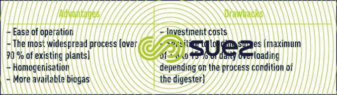
The advantages of anaerobic digestion are multipl
- Reduction of olfactory nuisances: fresh sludge from urban effluent is grey or yellowish; it contains faecal matter, vegetable waste, fibres. It stinks. Sludge that has been completely digested is black (iron sulphide) and gives off a slight tar-like odour.It is virtually impossible to distinguish their original constituents (with the exception of hair, fur, some seeds and plastic waste), 90% of salmonellae and most pathogenic germs are destroyed but virus and helminth egg elimination seems less satisfactory. If digested sludge is handled out in the open, this does not create any nuisances and upward fermentation does not appear even after long storage (unlike chemical or even aerobic stabilisation). Handling digested sludge in the open air does not result in any nuisances and no resumption of fermentation is observed even following a prolonged storage period (as opposed to chemical or even aerobic stabilisation).
- Sanitisation: 90% of salmonellae and most pathogenic germs are destroyed but virus and helminth egg elimination seems less satisfactory.
- Reducing the percentage OM in sludge: the elimination of a significant portion of OM via fermentation results in the global reduction in matter
If we call:
- m1 the percentage of mineral matter in fresh sludge (ratio to suspended solids);
- m2 the percentage of mineral matter in digested sludge (ratio to with suspended solids);
- the OM reduction x obtained through digestion can be calculated using the following equation:
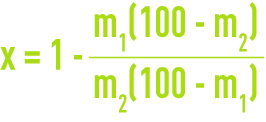
This equation is based on the assumption that mineral matter will preserved between the digester inlet and its outlet; it is an approximation as there are modifications, namely regarding carbonate concentration but it remains the simplest method to implement in the field.
For urban wastewater sludge, a reduction of between 40 and 50% in OM content namely corresponds to the elimination of one third of dry matter. Downstream dehydration, sludge drying or incineration facilities are reduced accordingly ; in addition, given the significant buffer capacity of the digester, sludge feeding can be perfectly regular (flow, concentration and quality).
Nb : experience shows that digesting a primary sludge does not improve its dewatering capacity - this also applies to biological sludge. On the other hand, the digestion of mixed sludge results in a loss in dewatering capacity which is all the greater given the large biological sludge / primary sludge ratio. This is due to a significant reduction in the proportion of organic matter from the biological sludge in the mix digested.
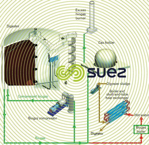
At an environmental level, digestion presents the advantage of providing energy in a storable form: biogas, which is usually produced in a quantity which is largely surplus to the thermal requirements of the digestion facility.
For example, when fresh mixed sludge at 70% OM/Suspended Solids is treated in a temperate zone, approximately 1/3 of the biogas produced suffices to heat the digester; 2/3 consequently remains available for energy generation.
Biogas therefore contributes towards the self-sufficiency of wastewater treatment facilities: fossil fuel consumption is reduced, the environmental footprint of facilities is also improved thanks to the lower volumes of sludge to be transported.
Biogas is generally stored in flexible gasometers or bell gasometers (in the vicinity of atmospheric pressure) or in gas spheres which are pressurized to several bars. In the event of biogas recovery (heating, drying, incineration, co-generation…), storage of between 6 and 8 hours is necessary.
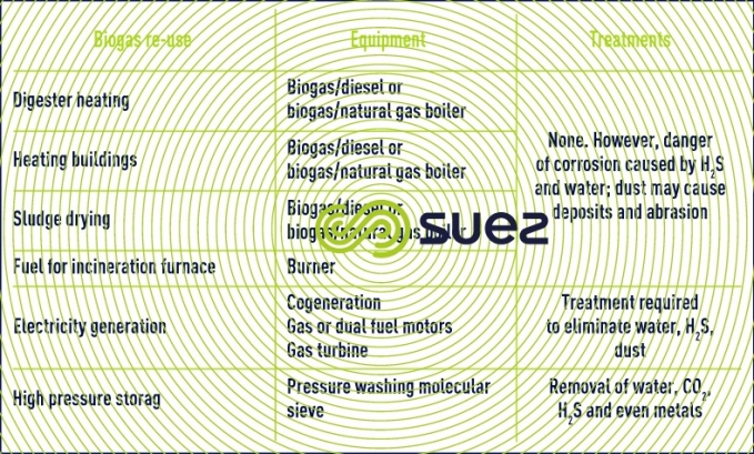
biogas re-use
Reminders: methane net calorific value = 35,865 kJ · Nm–3 (8,580 kcal · Nm–3); biogas net calorific value will vary depending on its methane content (the net calorific value of biogas containing 65% methane = 23,300 kJ · Nm–3 or 5,550 kcal · Nm–3).
recovery in the form of heat
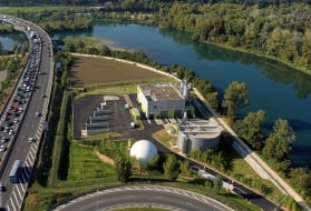
In this domain, the example of La Feyssine (Grand Lyon – France) is exemplary:
At this facility, which has a capacity of 300 000 PE, biogas production reaches 4187 m3 per day. Biogas is burnt in a boiler to heat the digesters and power the thermal sludge dryer ; 77% of the dryer’s energy needs are consequently met and the savings generated with respect to natural gas are to the order of 950 000 m3 per year.
simultaneous production of heat and electricity
When not used for heating purposes, the excess gas can result in the production of large quantities of electricity. Co-generation, using biogas fuel alone, simultaneously constitutes a source of heat and mechanical energy namely able to power generators; in relation to conventional thermal or electrical energy production systems, co-generation enables primary energy savings of approximately 35%.
Thus, a simple UWW primary settling plant with digestion can almost be self-sufficient in electricity. A wastewater treatment plant with biological treatment can achieve balanced energy usage when the aeration mode uses little energy (e.g. sludge activated by fine bubble air diffusion) and providing sludge treatment is kept simple.
Nevertheless, biogas recycling to produce energy often requires the inclusion of treatments designed to remove certain compounds in order to protect biogas motors or turbines.
biogas re-use example: cogeneration at the As Samra (Amman Jordannie) plant
The As Samra wastewater treatment plant which was conditioning in 2008, treats the wastewater of the agglomeration of Amman (Amman, Russeifa, Zarqa basin) where 60% of Jordan’s population resides. Its initial nominal treatment capacity of 267 000 m3/d was increased to 364 800 m3/d in 2015, representing 232 200 kg of BOD5.

The sludge treatment line includes seven 15 900 m3 digesters, each of which produces approximately 4500 Nm3 / h of biogas. Sulphur is removed from the biogas by means of a biological treatment, consequently reducing H2S content to less than 500 ppm. The biogas produced in the digesters is stored in three 5000 m3 gas reservoirs.
This biogas is transformed into electricity and heat via ten 1000 KWe biogas cogeneration units. The heat from co-generation is then used to maintain the temperature of sludge at 35-37°C in the digester.
A key point in ensuring the reliable functioning of co-generation using biogas is the quality of the biogas. For this, a biogas monitoring system is installed in order to control H2S and CH4 concentrations in the biogas powering the co-generation units. Regular analyses of biogas and motor oil are essential in order to check that the presence of these pollutants is limited to acceptable values. Total siloxane content measured in the biogas is less than 1mg /Nm3.
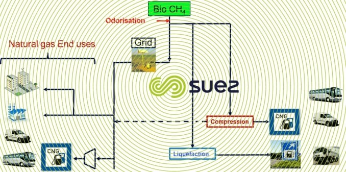
bio-methane production
What is bio-methane and what is it used for?
Bio-methane is produced by the biogas purification process with a view to its injection into the natural gas network or use as a fuel (figure 16).
Bio-methane composition must comply firstly with the requirements of the natural gas network, secondly with those of engine manufacturers.
Hydrogen sulphide, water and volatile organic compounds are generally separated during a pre-treatment stage.
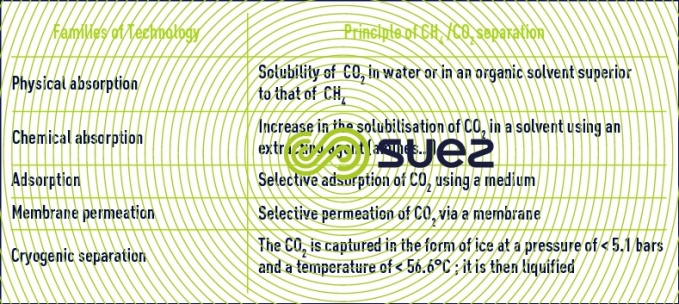
Once separated from methane using one of the technologies described in table 8, CO2 is evacuated in the « off gas ».

A diagram of the different possible uses for bio-methane as a natural gas or replacement fuel is set out in figure 17.
- The different technologies used to produce bio-methane
The main technologies used to separate CO2 from CH4 are summarised in table n° 8.
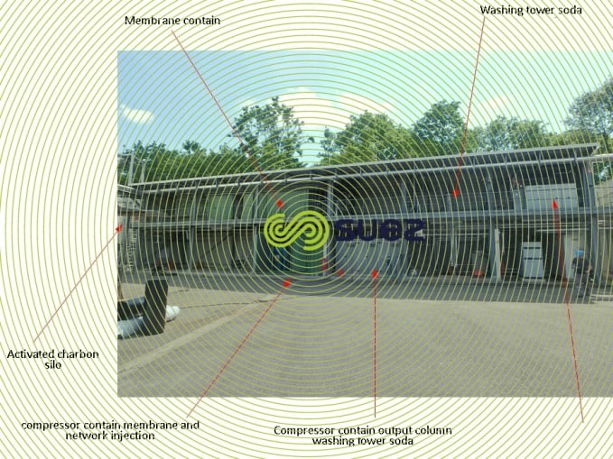
- Example of the bio-methane production unit at the Strasbourg wastewater treatment plant
The unit produces 450 Nm3 /h of bio-methane which is injected into Strasbourg’s natural gas network.
The technology used is gaseous permeation. Membranes have been provided by the company EVONIK.
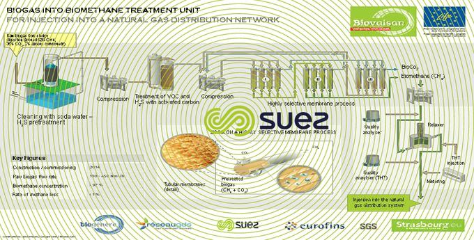
The hydrogen sulphide, water and volatile organic compounds are treated by a soda washing tower, activated carbon and drying stages using successive cooling. A final compression stage permits the pressure at the membrane treatment unit’s outlet to be adapted to network pressure.
sludge digester types and dimensioning
Degrémont®’s range of digesters:
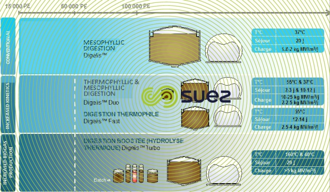
mesophilic digestion (35-40 °C): Digelis
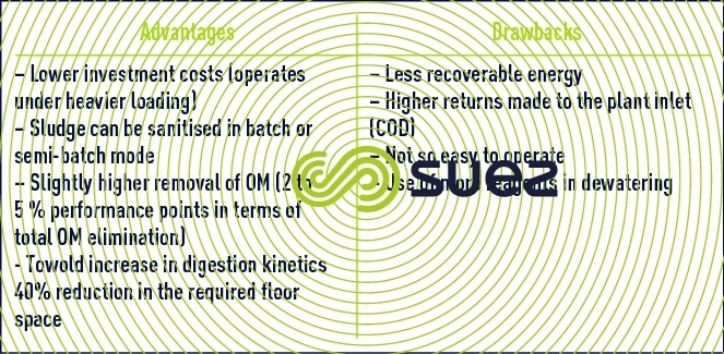
A mesophilic type sludge digestion system comprises one or more reactors in parallel, normally followed by a digested sludge storage tank used to adjust to the dewatering rate. Contact times and organic loading can be seen in figure 15 and the advantages and drawbacks are summarised in table 9.
thermophilic digestion (50-60 °C): Digelis Fast
A Digeslis Fast unit implements thermophlic digestion coupled with an energy recovery system at the digester outlet: thermophilic digestion accelerates the sludge digestion cycle whilst maintaining the same demand in energy as mesophilic digestion thanks to energy recovery.
two-phase anaerobic digestion: Digelis Duo
This is a simple process in principle because it is based on dissociating the two fundamental steps of anaerobic digestion: the hydrolysis/acidification step on the one hand and the methanogenesis step (production of CH4) on the other - see Anaerobic bacterial cultures.
These two stages are fundamentally different because:
- they do not make use of the same bacteria populations which do not share the same optimum operating conditions;
- each stage has different kinetics the bacteria responsible for acidogensis develop faster than those responsible for methanogenesis.
setting up
The dissociation of these two stages are dissociated in order to optimize their operation. The appropriate stability parameters for each are detailed below:
- Phase 1 – OM hydrolysis: HRT = 2 days on average, temperature 55 °C;
- Phase 2 – biogas production: HRT = 10 days on average, temperature 37 °C (producing excellent discharged OM stability).
This 2-phase system enables us to considerably reduce overall reactor capacity compared with classic digestion and also to better destroy the pathogenic germs that are present.
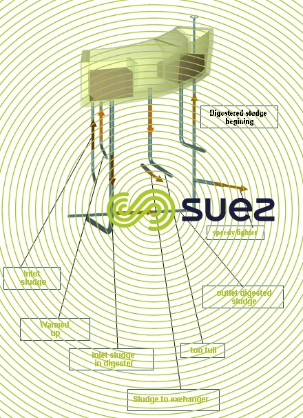
An intermediate exchanger between phase 1 sludge arrival and phase 1 sludge discharge will be required in order to cool the sludge before it reaches the second stage mesophilic reactor.
The heat recovered in this way will be used to pre-heat fresh sludge.
advantages of two-stage anaerobic digestion
In addition to reducing contact time and, therefore, digestion capacities, this process has further advantages:
- it will absorb much greater loading variations than the conventional process. This is not a negligible advantage given the range of sludge outputs recorded in wastewater treatment plants (rainy seasons, peak periods).Therefore, stage 1, dimensioned on average for a 2-day contact time, can go down to 1.5 days of contact time with the same effectiveness;
- it can be used to process more viscous sludge; preheated to 55°C, this sludge will, therefore, be more fluid and provide the mesophilic stage with a more stable input.
- this system produces a better quality of sludge during the second stage: after hydrolysis, sludge remains more fluid, even at 35°C, thus making mixing (homogenizing), easier.
When sludge undergoes a two to three day contact time at 55°C, most of the pathogenic bacteria, especially salmonellae, is destroyed; this is an important issue because it can have an effect on the post-treatments that will have to be put in place between dewatering the sludge and using it for agricultural spreading.
This process has the same overall effectiveness as conventional digestion for the same qualities and quantities of sludge to be treated.
The Digelis Duo process is of particular interest for increasing the treatment potential of an existing digestion unit by incorporating an upstream thermophlic digester (refurbishment). As an example, we can quote the Aix-en-Provence wastewater treatment plant.
In September 2002, the American body EPA (Environmental Protection Agency) granted PFRP equivalence to the 2PAD process (see sludge end uses), which is the name given to Digelis Duo in the United States: the sequenced operation of supply ensures the treatment of the entire sludge mass.
Among the facilities built in the United States, we can mention the Chattanooga facility (Tenessee) which treats the effluents of 1 600 000 PE, and includes 2 thermophilic digesters which feed 4 mesophilic digesters.

boosted digestion: Digelis Turbo
The Digelis Turbo unit integrates the thermal hydrolysis process developed by the Norwegian company Cambi upstream of a mesophilic digester.
Thermal hydrolysis consists in maintaining sludge with a DM concentration of between 16 and 17 % at a temperature of between 150 and 165°C for approximately 30 minutes, then carrying out flashing before feeding to the digester. Thermal hydrolysis has the objective of improving digestion performances on biological or mixed sludge by provoking the breakdown of bacteria’s cellular walls; cell content consequently becoming easily accessible to mesophilic digestion. Following hydrolysis, sludge is diluted to approximately 10% dry matter content before being injected into the digester: stirring the digester is effective in spite of this concentration as thermal hydrolysis improves sludge fluidity.
The advantages of Digelis Turbo are:
- A twofold decrease in digestion volume owing to a feed flow with a DM concentration of 10%;
- An increase of approximately 50% in the elimination of OM accompanied by an increase in biogas production of an identical factor;
- An improved dry matter content of dehydrated sludge to the order of between 4 and 8 % points;
- Sludge purification thanks to thermal hydrolysis.
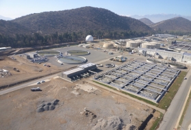
A major reference is the Mapocho plant (Santiago de Chile) : it consists in a facility with a treatment capacity of 760 000 m3 per day, for approximately 3.5 million inhabitants, representing 50 000 tons of DM per year. The choice of the Digelis Turbo technology has permitted the number of digesters installed to be reduced and will eventually permit a 6 % increase in electricity production and a 27 % fall in sludge production.
general dimensioning data
Table 11 recaps the dimensioning ranges normally applicable to sludge digesters according to the configuration selected:
degremont® sludge digester design
feeding and extraction
degremont® digesters are designed with a feed and extraction system via a basin which prevents gas being transported towards dewatering, ensures the digester is fed with sludge at the correct temperature and permits the gravity evacuation of the digested sludge.
digester stirring
Vigorous stirring is required to ensure:
- all added nutrients are brought into contact with the purifying biomass;
- temperature homogeneity;
- the accumulation of deposits is minimized.
- Biogas mixing
biogas mixing
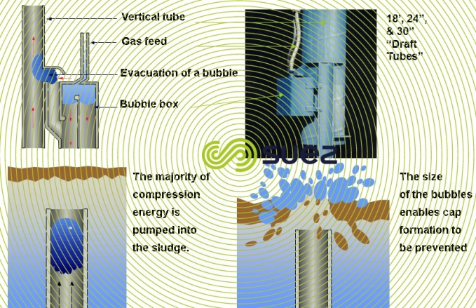
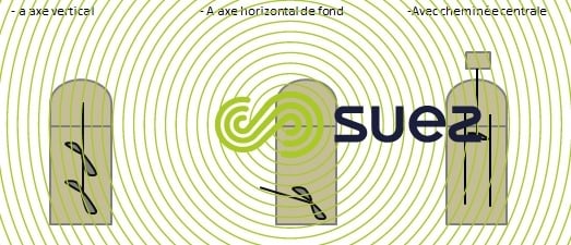
Biogas mixing is the most reliable technique (figure 23). Biogas is recirculated and injected into the mass of sludge under pressure. If this gas injection is concentrated in the central zone and at the base of the digester, subject to appropriate structure diameter/depth ratios, we will have a «toric» mixing effect from the centre outwards. At least 0.8 m3·m–2·h–1 of gas must be extracted from the digester dome for this mixing. SUEZ has standardised these mixing mechanisms that are equipped with dip tubes. This proven technology requires 5 to 6 W · m–3 in energy from the digester for biogas compression.
SUEZ has also developed the Cannon Mixer process: this biogas mixing technology consists in replacing injection pipes with «cannons» that are 450, 600 or 750 mm diameter tubes that draw up sludge from various points throughout the digester thanks to large bubble generators; this creates an energetic plug flow motion that is particularly effective. In particular, this technology can be submitted for digesters processing large amounts of sludge.
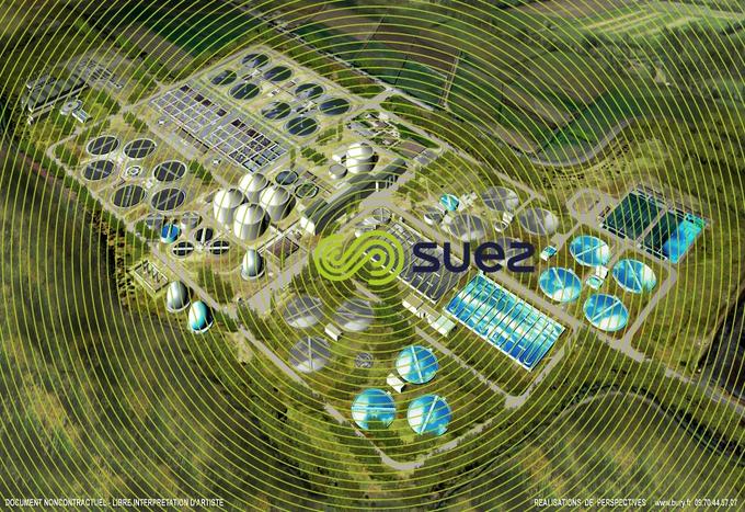
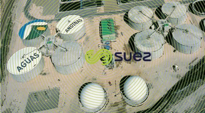
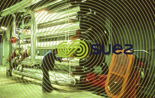
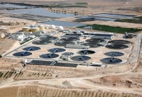
Well-dimensioned gas stirring permits digesters with a large horizontal section and a low-sloping invert to be put in place (Eight 16 000 m3 digesters with a 34m diameter at La Farfana in Chile, photo 14). The presence of a large free surface area facilitates deaeration and considerably reduces the risks of foaming (which namely exist during commissioning) on “vertical” type digesters, whilst limiting the formation of deposits in the digester thanks to homogeneous stirring. The cover most often takes the form of a fixed dome.
mechanical stirring
- The different types of mechanical stirring for digesters
This technology has to be applied subject to a minimum of precautions, i.e.:
- digester height/diameter > 1;
- sloping digester floor in order to limit the accumulation of deposits;
- effective sludge pre-treatment in order to eliminate fibres.
Failing these provisions, mixing may not have the requisite performance levels (limiting the digester's actual useful capacity) and may be difficult to implement (the need to withdraw the agitator moving components at regular intervals because they trap fibres).
The different types of mechanical stirring:
digester heating
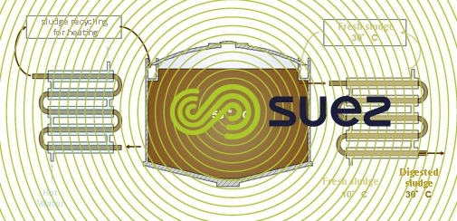
The safest heating method is that using external single tube exchangers fed with hot water and installed on the recirculation system of sludge undergoing digestion.
Spiral exchangers where the circulation velocity and the passage sections are the lowest can also be used subject to a few operating precautions (comminution, lack of spacers …).
In addition to heating fresh sludge, the heating system has to offset external heat losses. Transfer coefficients will vary according to the materials and to conditions governing their installation in the ground (N.B. the very adverse effect of a nappe bathing the base of a digester).
As a rough guide, in temperate countries, acceptable external heat losses will range from 2 100 to 2 500 kJ · m–3·d–1 (500 to 600 kcal · m–3·d–1) for capacities below 1 000 m3, and from 1 250 kJ · m–3·d–1 (300 kcal · m–3·d–1) for capacities above 3 000 m3.
Digesters usually have twin wall insulation; the air gap will either be left empty or filled with insulation (expanded material). Composite walls can also be found on large structures. In the case of small capacities, the concrete structure can be replaced with a suitably protected steel structure.
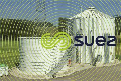
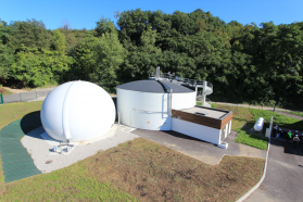
the Digelis Smart concept (figure 26)
The principle developed is to regroup sludge digestion and biogas storage functions in a same location in order to reduce both the floor space required and the biogas network. Consequently the digester dome is replaced by a flexible, double-membrane flexible gas tank with an interior membrane which reaches below the level of the sludge.
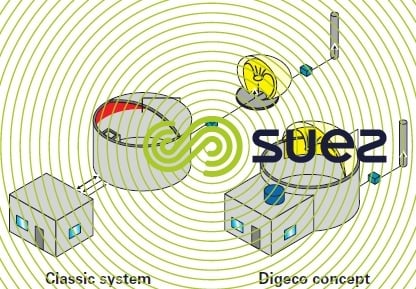
The Digelis Smart concept, which applies to mesophilic and thermophilic digestion, is namely well-adapted to facilities with a capacity of between 15 000 and 100 000 PE. The digester can be built in concrete but this size apparatus is particularly suited to metallic constructions on a concrete slab with a composite wall. In this case, the digester can be heated via a hot water network wound between the internal side and the external insulation of the digester.

commissioning and operating a digestion syste
general considerations
The general rules detailed in operating parameters regarding the control of single reactor methane fermentation unit apply.
Although it is not essential, seeding an anaerobic sludge digester reduces the time taken to reach the relevant loading levels (2 months to 1 month approximately). This is not as valid for digesters operating in thermophilic mode (flora has to be adapted to temperature conditions).
However, given the high viscosity of the suspensions, the role played by mixing is particularly important. Sludge mass mixing in a digester must be sustained continuously from the time biogas starts to be produced.
Biochemical reaction commencement is facilitated by a high concentration and it can be stated that, from an industrial viewpoint, a 15 g · L–1 concentration of DS constitutes the lower limit for residual urban sludge.
Heating a digester up to its nominal temperature, as soon as it is started up, is particularly recommended. Maintaining sludge pH to between 7 and 7.2 may require the addition of lime during the first few weeks.
digester foaming
Alongside random incoming air, foaming is one of the main malfunctions encountered in a digester. This phenomenon has several causes:
- the presence of filament forming bacteria (Nocardia, microtrix…) in aeration tanks (hydrophobic type bacteria that tend to agglomerate and float when found in a digester);this is the first cause to be considered;
- loading or flow rate surges;
- excessively high temperatures (>40° C);
- digesters that are fed with VFA-rich sludge that has already undergone significant fermentation;
- the presence of surfactants that are poorly or badly degraded in the water treatment line.
Foaming causes major operating problems (uncontrolled overflowing of digested sludge, loaded returns to plant inlet, blocked biogas circuits …).
These phenomena can appear in mesophilic or thermophilic conditions and regardless of the type of mixing system implemented (biogas or mechanical).
precipitations
In some specific cases – magnesium in wastewater (often caused by seawater entering into sewer mains) -, struvite is seen to precipitate (MgNH4PO4). This precipitation is responsible for blocking downstream sludge equipment (pipelines, exchangers, pumps …). Attention must be paid to the pH and this type of problem can be resolved by injecting iron salts to block the phosphates (FePO4).
Struvite precipitation can be voluntarily triggered and controlled in a structure downstream of the digester, namely in order to recover phosphorous which can be transformed into fertiliser.
drainage
The periodic drainage of sludge digesters (10 to 15 years, between two cleaning interventions, depending on the quality of the pre-treatments put in place and the chosen stirring mode), must be part of the normal maintenance programme in order to evacuate sand and silt which, in the long-term, accumulate in the bottom of structures and reduce their useful capacity. Meticulous sand removal from raw water is always recommended.
processes likely to improve anaerobic digestion performance
A certain number of pre-treatment technologies have been developed in order to improve the performances of anaerobic digestion:
There are many objectives:
- eliminating greater amounts of organic matter (removing less sludge from the plant) and increasing biogas output (in situ recycling);
- enhancing reaction kinetics and reducing reactor capacities (lower investment costs).
- With the exception of the thermal hydrolysis process described within the context of the Digelis Turbo, the effectiveness of these pre-treatments has been unable to be proven on an industrial scale.
co-digestion
Co-digestion consists in digesting sludge from urban wastewater treatment facilities and other organic waste in a same reactor : greases, the fermentable fraction of domestic waste (vegetal waste…) ; by-products from the agri-food industry (lactoserum, breeding effluents…), external sludge. The co-entrants selected are preferably entrants with a high methanogenic power in order to boost biogas production.
Co-digestion requires a good deal of rigour in the collection, sorting and preparation of organic waste prior to its addition to the digester.
Bookmark tool
Click on the bookmark tool, highlight the last read paragraph to continue your reading later
